Homework #5
Guidelines
- Complete your work on green engineering paper
- Staple in upper left if more than one sheet.
- Format the top of the first sheet as follows.
| ECE 383 | [Your name] | HW#1 | [Due Date] | [Page ref]
|
The page reference for the first page of a four page document would be 1/4, the
second page of this document would be labeled 2/4 and so on.
- Do not write on the back side of the green engineering paper
- Digital copies of all code, testbenches, and waveforms will also be submitted via BitBucket.
- Draw a detailed diagram of the oscilloscope grid required for Lab1. A detailed
diagram must be drawn on green engineering paper and include
- (x,y) corners of the monitor.
- (x,y) each of the four major corners (already given).
- y-coordinates for all the major horizontal grid lines.
- (x,y) coordinates for one set of three horizontal of hatch marks.
Indicate with an arrow which set of three.
- x-coordinates for al the major vertical grid lines.
- (x,y) coordinates for one set of four vertical of hatch marks.
Indicate with an arrow which set of four.
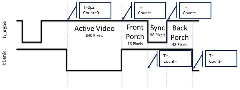
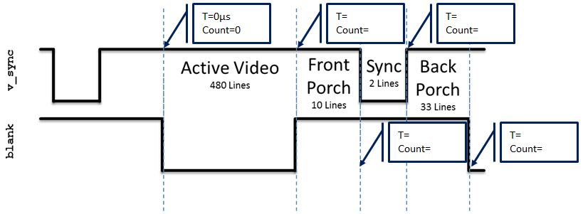
- Given that the pixel clock is running at 25Mhz, add the durations and counts of the
h_synch and v_synch signals show in Lab1. Set time=0 on the blue dashed line
on the left side of the region labeled "Active Video". You should add durations
and counts for all blue lines.