| Date: | February 14 |
| Lecture: | 11 |
| Homework | HW #7 |
| Handout | hand11.pdf |
| Code | lec11.vhdl lec11_tb.vhdl |
| Lesson Slides | CSCE_436_Lec11.pptx |
Generics
There are times when you will want to parameterize your designs (i.e. make them like functions). A good example is when you have a variable bus width of a component like a counter. Instead of having multiple VHDL sources files for a 5-bit-counter, 16-bit-counter, etc., it would be far easier to have a single definition for an N-bit-counter and somehow specify N when you went to instantiate the counter. Fortunately, generics in VHDL give us this capability. The files linked above are an N-bit counter and its testbench. This example should give you a pretty good idea of how to use generics.Entity Declaration
entity lec11 is
	generic (N: integer := 4);
	port(	clk: in  STD_LOGIC;
		reset : in  STD_LOGIC;
		crtl: in std_logic_vector(1 downto 0);
		D: in unsigned (N-1 downto 0);
		Q: out unsigned (N-1 downto 0));
end lec11;
Note:
- The variable N is available in the entity and architecture context. In this case, you will need it to define the width of vectors.
- The value of N must be an integer, not a binary string. Just use positive integers for N.
- The default value for N is 4. That means, if you do not use the generic map statement in the instantiation below, you will get a 4-bit counter.
- The D and Q vectors use N-1 because the vector starts at 0.
   uut: lec11
	generic map(5)
	port map (  clk => clk,
          	    reset => reset,
		    crtl => crtl,
		    D => D,
		    Q => Q);
In this case, I made a 5-bit counter. The testbench linked above runs the counter
through all four control modes and even shows how it rolls over (around 7.5uS).
A picture of the run of the testbench can be seen below.

Datapath and Control
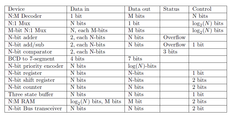
The design methodology of separating the datapath and control units breaks the design of digital systems into two components: a datapath and a control unit. The datapath is responsible for all the data manipulations and the control unit is responsible for sequencing the actions of the datapath. The datapath is constructed from basic building blocks.A digital system built using the datapath and control design approach is still a digital system whose inputs and outputs can be categorized into Data Input, Data Output, Control and Status. The digital system shown below consists of two components, a datapath and a control unit.

Design Process
Building digital systems using the datapath and control approach is a three- step process:- Write an algorithmic description for the solution to the problem.
- Parse the algorithmic description into datapath building blocks and control states.
- Define the MIEs and OEs for the control unit.
The programming language used to formalize an algorithmic solution to design problem is a derivative of the popular C-programming language referred to as mini-C. The mini-C programming language contains four types of statements.
- IF
- if (condition) then BODY_1 else BODY_2
- FOR
- for (i = A; i < B; i += 1) BODY
- WHILE
- while(condition) BODY
- ASSIGNMENT
- X = value
In digital circuit design, the variable types in the mini-C language are limited to be either binary or 2's-complement integers. Arrays of these types are common. Limiting the discussion to integer types is not an inherent limitation of the mini-C language, rather it limits the discussion to the essential points of the design process. Complex types like floating-point numbers can be accommodated if the necessary representations and hardware are developed.
No effort is made to explain the process of transforming a word statement into an algorithm; the process should be a familiar task from writing programs. Rather, consideration of the transformation of the algorithm into hardware is presented.
From an algorithmic statement, its conversion into hardware is desired. The conversion is accomplished by parsing the algorithm. In computer science, parsing is the process of analyzing a program for its structure. Here, parsing means analyzing a program line-by-line, sequentially, from the first line to the last line, to determine its hardware structure. The analysis process takes a line of code, a mini-C statement, and transforms it into some additional building blocks in the datapath and some additional states in the control unit. When the parsing is complete, the datapath has all the functionality present in the algorithm, and the control unit has all the control structures present in the algorithm.
IF
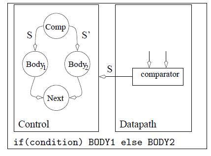
When an if/then/else statement is encountered in a program, BODY_1 is executed when the condition is true. If condition is false, then BODY_2 is executed. BODY_1 and BODY_2 contain 0 or more statements. Typically, the datapath computes the condition using a comparator. In such a case, the datapath requires a comparator, the output of which is the status signal shown in Figure 11.1.While the control unit is in state IfThen, the condition is being evaluated, the status signal is being communicated to the control unit, and the control unit is deciding whether to transition to either the BODY1 or BODY2 states. When the clock edge arrives, the control unit will transition to its next state. The BODY1 or BODY2 states contain the entire collection of states derived by parsing all the statements in their respective bodies. Regardless of which path the control unit takes, both threads return to the Next state, which is the next statement after the if/then/else statement in the algorithm.
FOR
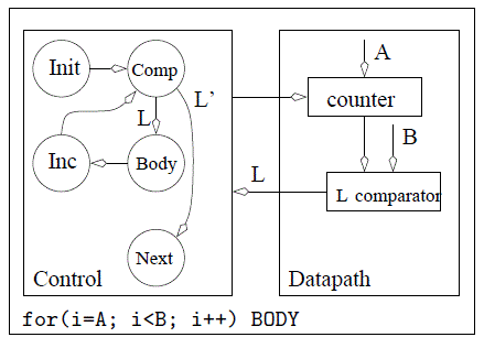
When a for loop is encountered in a program, BODY is executed B-A times and the value of i is available for use inside BODY. BODY contains zero or more statements. A for statement requires a counter and a comparator arranged as shown in Figure 11.2. The initial value of the for loop is the data input to the counter. The output of the counter is the i variable of the for loop. The i variable is compared to the terminal value of the for loop. The status of this comparison is passed to the control unit so that the control unit knows to terminate the for loop when the counter has reached its terminal value.The control unit sequences the actions of the hardware in the datapath. The execution of the for loop begins with an initialization of the counter in the Init state. In this state, the control unit asserts a load signal on the control lines to the counter causing the counter to be initialized to A. On the next clock edge, the counter loads A and the control unit transitions to the Comp state. In this state, the control unit does nothing, giving the comparator time to determine the relative magnitude of i and B, and to assert its L output to the control unit in the form of a status signal. The control unit uses the status signal to either execute the body of the for loop, or to exit the for loop and proceed with the next instruction after the for loop. The Body state represents the collection of states derived by parsing all the statements in the body of the for loop. At the end of the for loop's body, the control unit enters the Inc state where the control unit asserts an increment signal on the control lines to the counter. This assertion causes the counter to count up on the next edge which also causes the control unit to transition back to the Comp state.
WHILE
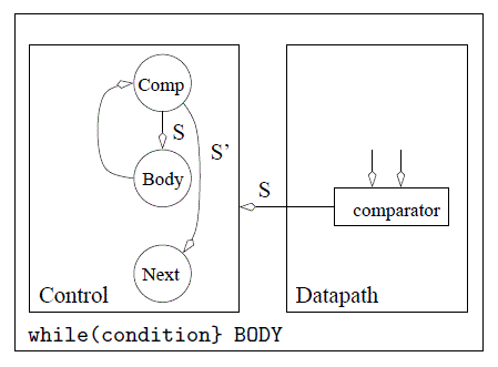
When a while loop is encountered in a program, Body is executed while the condition is true. Typically, the datapath computes the condition using a comparator, the output of which is the status signal shown in Figure 11.3. While the control unit is in state Comp, the condition is being evaluated, the status signal is being communicated to the control unit, and the control unit deciding on whether to transition to either the Body or Next states. The Body state represents the collection of states derived by parsing all the statements in the body of the while loop.In some cases the status signal may be determined by some external source. Then, the status line shown in Figure 11.3 as emanating from the datapath would in fact be sent in from the external world as shown in Figure 11.3.
ASSIGNMENT
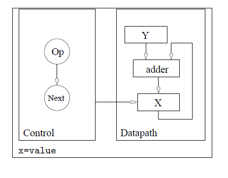
When an assignment statement is encountered in a program, X is assigned a new value. This statement is realized by placing a register in the datapath whose input is the value on the right-hand side of the assignment statement. In order to make the assignment, the control unit enters the Op state, where it asserts a load signal on the registers control input. On the next positive edge of the clock, the register loads its value and the control unit moves on to the Next state. The size of the register storing X is determined by the range of values required to be stored in X. In some cases, this size is defined by the word statement; in other cases, the designer must make a judgment call on a reasonable value range.Statements like X = X+Y often occur in algorithms. In cases when a variable appears on both the left-hand and right-hand side of an assignment statement, feedback must be employed as shown in Figure 11.5. In this case, the output from the X register is added to Y, the output of the summation is sent to the data input of the X register. The control unit asserts a load signal on the X register's control input when it is in the Op state. Most likely, the control unit would assert a hold signal on the Y register's control input while it was in the Op state.
What prevents the X register from rapidly adding Y to itself multiple times? The answer is that the X register will only latch X+Y on the positive edge of the clock. So X+Y cannot "get into" the X register until the positive clock edge.
Basic Building Blocks
