Homework #7
Guidelines
- Complete the answers using the Canvas Quiz
- Digital copies of all code, testbenches, waveforms, etc will be submitted via Canvas and BitBucket.
-
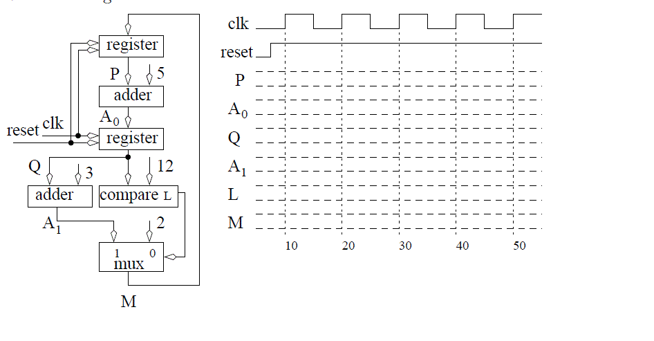
Complete the timing diagram below assuming that the register is
positive edge trigger and has an asynchronous active low reset.

- In an ideal world when the button on the Nexys Video board were pressed,
the output go solidly from ground to 5 volts. Unfortunately, push-buttons
are mechanical devices with contacts that literally bounce when contact
is made and broken. This bouncing will cause the voltage to oscillate
several times times in quick succession.
Switch bouncing is a major problem in digital circuits because the
circuit sees the signal change several times and may take actions appropriate
for each of these bounce values when the user only intended a single actions
to take place. Your task in this problem is to implement a version of a clever
technique used by one of the students in our class to solve it for Lab 1.
Design a FSM machine that looks at left and right directional buttons and counts up
once only after a two button sequence is pressed. The sequence is
left button, press and release and the right button is press and release. Use
the generic counter linked in lecture 11 to instantiate a 3-bit counter.
Your testbench should show the following button press sequence:
left (press then release), brief pause,
left (press then release), brief pause,
right (press then release), brief pause,
right (press then release), brief pause,
left (press then release), brief pause,
right (press then release) brief pause.
The brief pause between the presses is meant to simulate a switch bounce
when, for example, one left button press is followed immediately by
another left button press. In order to
effectively simulate this phenomena, the brief pause must be longer
than a single clock cycle.
Turn in:
- The state diagram for your FSM (neatly hand drawn is fine).
- A digital copy via Canvas and BitBucket of the VHDL describing your FSM (include a proper header).
- A digital image via Canvas and BitBucket of your testbench
output in Vivado Simulator showing the following signals - remove all other signals.
- clk
- reset
- FSM state
- left and right button
- Count value
