| Date: | January 24 |
| Lecture: | 3 |
| Next lecture | HW#3 |
| Status: | Complete |
| Code | lec03.vhdl lec03_tb.vhdl |
| Handout | hand03.docx |
| Lesson Slides | CSCE_436_Lec3.pptx |
Synthesis
Lets consider how we could synthesize the majority circuit. The essential observation is that we need to create an association between the entity specification of the majority circuit and the pin-out of the Xilinx chip. Our Xilinx chip is an Artix-7 FPGA (Xilinx part number XC7A200T-1SBG484C), 484 pin, SGB484 Package and can be found here on page 80. The designers of the Nexys Video board decided to connect some of these pins to specific hardware modules. These connections are described in the Nexys Video Board Reference Manual. Of interest are the connections described on pages 19, highlighting the switches and LEDs on the board.We would like the input to our majority to come from the DIP switches and the output to go to an LED. Making some arbitrary choices, let's make the associations shown in the following picture.
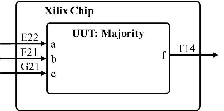
This is accomplished by inserting the following code into a constraints file called majority.xdc (formerly called .ucf files with the old ISE software) and adding it to your project (with an implementation association).
# This is slide switch SW0
set_property -dict { PACKAGE_PIN E22  IOSTANDARD LVCMOS12 } [get_ports { a }]; #IO_L22P_T3_16 Sch=sw[0]
# This is slide switch SW1
set_property -dict { PACKAGE_PIN F21  IOSTANDARD LVCMOS12 } [get_ports { b }]; #IO_25_16 Sch=sw[1]
# This is slide switch SW2
set_property -dict { PACKAGE_PIN G21  IOSTANDARD LVCMOS12 } [get_ports { c }]; #IO_L24P_T3_16 Sch=sw[2]
# This is LED Led(0)
set_property -dict { PACKAGE_PIN T14   IOSTANDARD LVCMOS25 } [get_ports { f }]; #IO_L15P_T2_DQS_13 Sch=led[0]
Standard Combinational Elements
There is a common error that may come up in your design: you cannot use a variable listed on the entity as an out port on the right hand side of a signal assignment statement. As an example, the code below would not work because of the statement not_q <= not q;.
entity circuit is
    port (clk, data: in std_logic;
	  q, not_q: out std_logic);
end circuit;

architecture error of circuit is
begin
    q <= some cool logical stuff using clk and data;
    not_q <= not q;
end error;
The solution is to make a signal called temp and then assign
"some cool logical stuff using clk and data" to
that temporary variable. Then, the code would look like:
    temp <= some cool logical stuff using clk and data;
    q <= temp;
    not_q <= not temp;
Mux using CSA
Using a conditional signal assignment statement greatly simplifies the design of muxes. In the example below, the signals x, y0, y1, y2, and y3 could be std_logic or std_logic_vector. The select signal S must be defined as std_logic(1 downto 0);x <= y0 when S = "00" else y1 when S = "01" else y2 when S = "10" else y3;
STD_LOGIC_1164 and NUMERIC_STD
Up to this point, we have used the STD_LOGIC_1164 library and its associated 9 values (see the "Important Notes" section of lecture 1), primary sticking with '0' and '1' along with the logic operations AND, OR, and NOT. All this functionality is made available when you put the following two lines at the top of your file:library IEEE; use IEEE.STD_LOGIC_1164.all;It is worth a few minutes to look at the contents of the STD_LOGIC_1164 library at this link. For all its power, the STD_LOGIC_1164 library does not support numerical values and numerical operations like addition and comparisons. That is, if you wanted to add two STD_LOGIC_VECTOR's together, you wouldn't be able to do it. This is where the NUMERIC_STD library comes in. The NUMERIC_STD library supports two main datatypes: unsigned and signed, as well as a host of operations. It's worth a few minutes to look at the contents of the NUMERIC_STD library file at this link. Example code which uses the NUMERIC_STD library is shown below. Notice how the entity inputs and outputs are declared using signed and unsigned datatypes rather than STD_LOGIC_VECTOR.
library IEEE;
use IEEE.std_logic_1164.all;
use IEEE.NUMERIC_STD.ALL;

entity lec3 is
	port(	au, bu:	in unsigned(3 downto 0);
			cu,du,su:	out unsigned(3 downto 0);
			as, bs: in signed(3 downto 0);
			cs,ds,ss:	out signed(3 downto 0));
end lec3;

architecture structure of lec3 is

begin

	cu <=	"1000" when (au > bu) else
		"0110" when (au = bu) else
		"0001";
	su <= au + bu;
	du <= au - bu;

	cs <=	"1000" when (as > bs) else
		"0110" when (as = bs) else
		"0001";
	ss <= as + bs;
	ds <= as - bs;

end structure;
In the simulation below, you can see how the values of the signals are correctly updated based on the operations performed.
From here on out, your program may only have two main datatypes, STD_LOGIC_VECTOR and UNSIGNED (this is all you will need). However, there will be times when you need to convert between these two representations. The following code snippet shows how this is accomplished. The process is similar to typecasting in C or another software-driven language.
	a: std_logic_vector(7 downto 0);
	b: unsigned(7 downto 0);
	c: std_logic_vector(7 downto 0);

	b <= unsigned(a);
	c <= std_logic_vector(b);
Notice that if we tried to set up the assignment b <= a or c <= b without typecasting, we would get an error.
Combinations
One of the most common logic structures you will encounter is a conditional statement in the form of if-then-else. While this statement can be directly implemented using the CSA discussed in lecture 2, it's important that you have some appreciation of how this construct is realized so that you can better arrange your circuit to reduce the logic required.All conditional statements consist of three parts: the condition to be checked (the if clause), the statement to be evaluated when the condition is true (the then clause), and the statement to be evaluated when the condition is false (the else clause).
Typically, the condition being evaluated seeks the relative magnitude of two unsigned binary numbers, requiring a comparator. The then and else clauses will typically require some logic or arithmetic operation. In order to illustrate the hardware realization of a conditional statement, consider the following example.
C:	if (a<4) then z=y+3 else z=y+7
VHDL:	z <= y+3 when (a < 4) else y+7;
The following hardware schematic realizes this
However, this circuit is not minimal; one of the adders can be removed. This can be done by realizing that the y input to the adders is constant. Therefore, we could have muxed through 3 or 7 into an adder with y on the other port. You will practice this more in the homework.