Homework #5
Guidelines
- Complete the answers using the Canvas Quiz
- Digital copies of all code, testbenches, waveforms, etc will be submitted via Canvas and BitBucket.
- Draw a detailed diagram of the oscilloscope grid required for Lab1. A detailed
diagram must be drawn on green engineering paper and include
- (x,y) corners of the monitor.
- (x,y) each of the four major corners (already given).
- y-coordinates for all the major horizontal grid lines.
- (x,y) coordinates for one set of three horizontal of hatch marks.
Indicate with an arrow which set of three.
- x-coordinates for all the major vertical grid lines.
- (x,y) coordinates for one set of four vertical of hatch marks.
Indicate with an arrow which set of four.
- (x,y) coordinates for the nine pixels of the trigger volt mark in reference to
the tr_volt signal.
- (x,y) coordinates for the nine pixels of the trigger time mark in reference to
the tr_time signal.
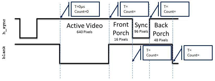
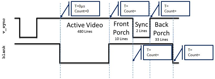
- Given that the pixel clock is running at 25Mhz, add the durations and counts of the
h_synch and v_synch signals show in Lab1. Set time=0 on the blue dashed line
on the left side of the region labeled "Active Video". You should add durations
and counts for all blue lines.