| Date: | February 24 |
| Lecture: | 18 |
| Homework | HW #9 |
| Status: | Complete |
| MicroBlaze Tutorial on Digilent Website | MicroBlaze Tutorial |
| MicroBlaze Tutorial with CSCE 436 Deviations | MicroBlaze Tutorial |
| Supplemental Lesson Slides | CSCE_436_Lec18.pptx |
| Code | Lec18.c (Initial Hello World) Lec18_v2.c (Example code to interface with GPIO LEDs |
MicroBlaze
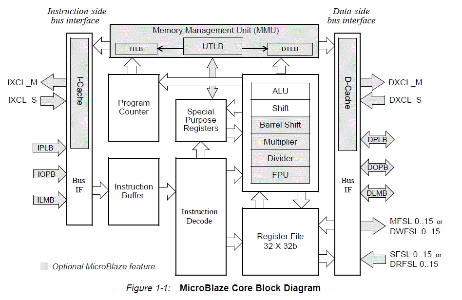
The goal of today's class is to bring you up to speed on how to instantiate a microBlaze processor on our Artix 7, integrate a custom piece of VHDL code to the processor, and then to write some C code to run on the microBlaze to control the custom VHDL module. Here are some specifications on the microBlaze processor:- It has thirty-two 32-bit general purpose registers.
- It uses a 32-bit instruction word with three operands, and has two addressing modes.
- It has a 32-bit address bus.
- It uses a single issue (3 or 5)-stage pipeline.

The rest of the class will be devoted to getting the microBlaze to work.
Tutorial Overview
In this tutorial, you will be introduced to the tool flow for simple MicroBlaze designs. Specifically, you will create a design that continuously reads the input from UART and writes that value to the LEDs. The UART will be connected from the FPGA to your computer via a micro USB cable.
You will follow the tutorial here step by step.Deviations from the Tutorial
- Call your project "L18" or "Lesson18".
- Keep in mind that you can zoom in and out on your block diagram.
- The AXI bus is the bus the Microblaze uses, similar to a PCI bus in normal PC's.
- What does the UART actually do? Although you learned about it in ECE382, you can read more about UART's
for a referesher. - UART Controller?
- Ignore step 6.3 completely. When you do step 6.2, just check the "reset" box in the automatic connections dialogue under clock wizard. You do not need to make the connection manually.
- The Memory Interface Generator (MIG) is used essentially add BRAM (it is SDRAM in this case).
- Although you didn't need to make the first conneciton manually, you do need to make the 2nd connection manually (with the RAM).
After Completing the Tutorial Hello World
Once you complete the MicroBlaze Tutoral and get Hello World to display on your terminal. This will allow you to echo values received on the UART
lec18.c code at the top of the page to your main.c in your SDK project.xuartlite_l.h file to see the different options you have to read from and write to the UART.
These are just simple macros that provide you shortcuts to perform memory operations. All of this should be review from when we first introduced you to the C programming language.Update Hardware/Software for LED GPIO
Finally, you will write software that reads in a value from UART, echoes that value to the UART and LEDs.
- Confirm that you want to import the new bitfile and design to your SDK project.
- Add the code found in the
lec18_v2.cfile to yourmain.c, where you deem appropriate:
xgpio.h file to see the different options you have to read from and write to GPIOs.
These are just simple macros that provide you shortcuts to perform memory operations. Conclusion
We have covered quite a lot of ground in this tutorial. It is critical that you understand each step of this development process, as this is critical to your next lab and the final project. Be sure you ask your instructor if you are unsure about anything we covered in this tutorial. Specifically, you should understand the following:
- Create an embedded MicroBlaze hardware platform with Xilinx Vivado
- Add a standard GPIO component:
- Connect it to the MicroBlaze AXI bus
- Configure its memory-mapped address
- Connect input/output ports to FPGA pins
- On Lesson 19 we will reaccomplish the tutorial in a new project and then create and add a custom peripheral:
- Make individual read/write registers available from software
- Structurally add additional VHDL modules in separate files
- Write software to interface with any given MicroBlaze peripheral. In particular, you should be able to write to and read from the peripheral software registers.
- Test and debug your software/hardware on the FPGA.