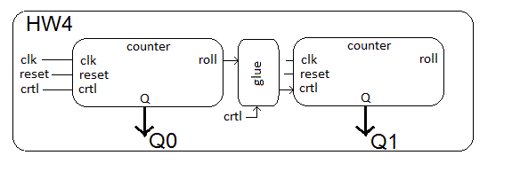
Instantiate a pair of cascaded counters, similar to those in Figure 13.2
of the text. The pair of counters operate in a coordinated fashion, with one
counter representing a least significant value, and the other a most significant
value. When the least significant counter is going to roll over, the most
significant counter will count up by one. At no other time will the most
significant counter increment.
You should have one counter that operates according to the
following truth table.
| clk | reset | ctrl | Q+
|
| 0,1,falling | x | x | Q
|
| rising | 0 | x | 0
|
| rising | 1 | 0 | Q
|
| rising | 1 | 1 | Q+1 mod 5
|
You should instantiate this counter twice and add some glue logic between
the two devices so that the most significant counter counts up only when the
less significant counter is going to roll over. Include the truth table for
the glue logic as an explicit comment in your VHDL code. The high-level
architecture for this assignment is given in the block diagram below. Please
note that the "roll" signal coming from the counter probably should not
be included in your counter, rather it would be easier to realize as a
a combinational logic statement along side the two counter instances.

The top level entity description should look like the following. When
ctrl = '1', the counters are enabled to count up as a cascade pair, and
when ctrl = '0', the counter should hold their value.
entity hw4 is
        port(	clk, reset: in std_logic;
		ctrl: in std_logic;
		Q1, Q0: out unsigned(2 downto 0));
end hw4;
Turn In
- A hardcopy (plus digital copy via BitBucket) of your VHDL code, testbench, and waveform (include a proper header).
- Neatly draw the Circuit Diagram for your cascade counter.
- A testbench exercising the cascade pair. It must:
- Hold the least significant counter at 4 for one
clock cycle (using ctrl='0').
- Roll over the most significant counter once.
- Show clk, reset, Q1, Q0, (least significant) roll
signal, and the ctrl input to the most significant
counter.
- Remove all junk signals.
- Fit waveform on one page.
Testbench Tip
In order to test your cascade counters, you will need to apply a complex
test sequence to the control signal. The following VHDL code in your
testbench will help achieve this. This is CSA version of the process
structure given in section 2.2.4 of the textbook.
ctrl <= '1', '0' after 15us, '1' after 16us, '0' after 17us, '1' after 18us;
Check out the testbench linked at the top of lecture 4 for more details.
