| Date: | February 27/28 |
| Lecture: | 19 |
| Homework | HW #11 |
| Status | Complete |
| Code | lec19.c |
| Tech Docs | OS and Libraries Document Collection MicroBlaze Processor Reference Guide |
| Lesson Slides and Tutorial | ECE_383_Lec19.pptx |
Interrupts
Interrupts are used when you want to your system to do more than one thing at a time. An interrupt service routine (ISR) is a subroutine called by hardware. The following figure illustrates the process of "calling" and returning from an ISR.
- MCU powers up, jumps to RESET vector
- MCU starts execution of main
- Dynamic configuration
- configure hardware
- clear hardware interrupt flag
- enable hardware interrupt
- Event occurs which sets interrupt flag
- MCU stops running main
- MCU saves PC
- MCU disables interrupts
- Executes "GOTO ISR" at interrupt vector address
- ISR: Poll interrupt flags
- ISR: Execute appropriate code in ISR
- ISR: Clear interrupt flag
- ISR: executes rted
- Interrupts are enabled
- PC is restored
- MCU resumes running main
Interrupts in the MicroBlaze
Today we will examine how to generate an interrupt into the MicroBlaze. This will require three ideas to come together. First, hardware to generate an interrupt. For the example today we'll be using the counter from hw10 to generate an interrupt in the MicroBlaze. We will have to understand how to route the roll signal to the MicroBlaze. Second, we will need to configure the Vivado tool to recognize the roll signal as an interrupt. This will require making connections in the design block digram file. Third, we will need to understand how to write our C code to respond to the interrupt signal generated by our counter.Modify the counter
In HW#10 you modified the counter to assert the roll signal when the count is at the maximum value. For the sake of this lecture, we will assume that you put your HW#10 solution in a file called lec19.vhd. The roll signal must be sent to the MicroBlaze by routing it through both the user_logic and counter interfaces. This is illustrated in the following figure.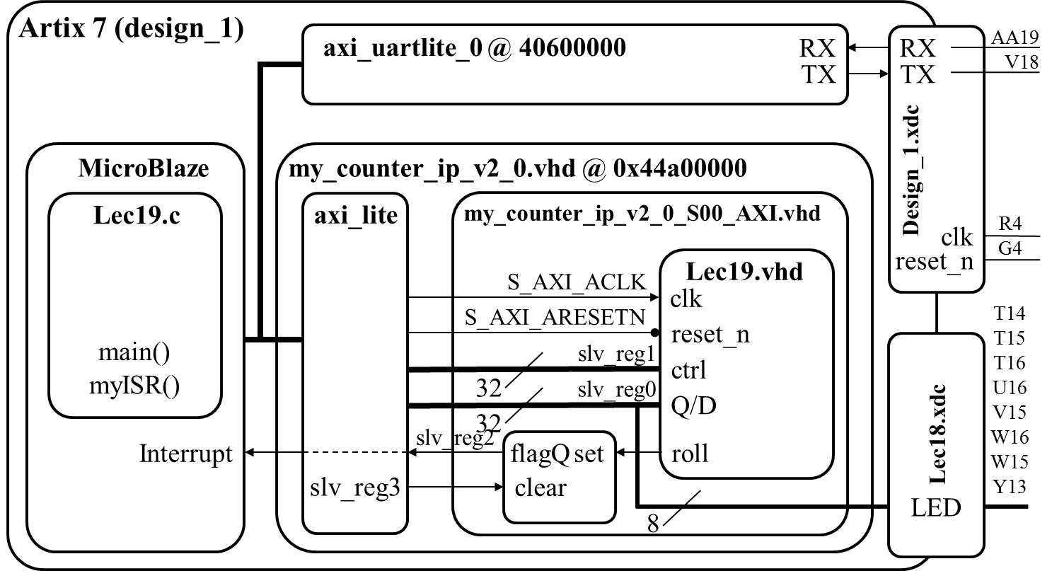
You should notice that the roll signal will go through all the same interfaces as the LED signal. The important distinction is that the roll signal will not be output from the Aritx 7 chip and as a consequence, the roll signal will NOT appear in the system.xdc file. Instead it is routed to the MicroBlaze in the following step.
Configure the interrupt signal
You will have to either edit or create a new IP Package with the modified counter from HW#10. I chose to create a new one. You will use the roll signal created in HW#10 to generate an interrupt on the MicroBlaze soft core. You may have to register the roll signal long enough for the MicroBlaze to register the interrupt similar to the flag register you created in Lab 2 (shown in block diagram). Once created you will add the IP core to your IP design and connect the Roll signal to the MicroBlaze Interrupt input. Click the "+" sign (1) by the MicroBlaze to connect the Roll Signal(2) to the MicroBlaze Interrupt input (3) directly instead of going through the interrupt controller.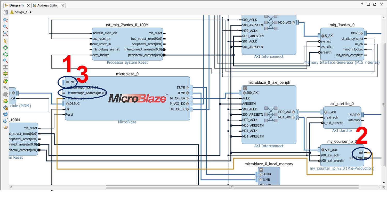
C programming
In order to understand how interrupts are handled by the MicroBlaze, its important to understand something about the hardware. I found most of the following information in the MicroBlaze Users Guide.- The Machine Status Register contains control and status bits for the processor. Bit 30 of this register, IE, is the interrupt enable.
- The MicroBlaze is a three stage pipeline machine - interrupts will need to flush the pipe before proceeding.
- The interrupt vector is located at address 0x10-0x14 in memory.
- MicroBlaze supports a single interrupt source.
- When an interrupt occurs, the following actions happen.
r14 <- PC
PC <- 0x00000010
MSR[IE] <- 0
- When the interrupt service routine terminates, control is turned over to the instruction at address r14 and MSR[IE] is set.
//--------------------------------------------------------------------
//-- Name:	Maj Jeff Falkinburg
//-------------------------------------------------------------------------
#include <xil_exception.h>

void myISR(void);

int main(void) {

    microblaze_register_handler((XInterruptHandler) myISR, (void *) 0);
    microblaze_enable_interrupts();

    stuff();

} // end main


void myISR(void) {
	isrCount = isrCount + 1;
    Xil_Out8(countClearReg, 0x01);					// Clear the flag and then you MUST
	Xil_Out8(countClearReg, 0x00);					// allow the flag to be reset later
}
There may be occasion for you to examine the compiled assembly language for
the MicroBlaze. To do this open the lec19.o file located in your project folder
Debug -> src -> lec19.o You will find the
MicroBlaze Processor Reference Guide handy to interpret the instructions.
Manual Easter-egg Hunt
Consult the MicroBlaze Processor Reference Guide and convert the- addik r22,r19,1
- swi r23, r1, 60
- bgei r18, -44
- What string formats are supported by the xil_print instruction?