*arg max
*arg min
CSCE 236 Embedded Systems, Spring 2016
Lab 1
Thursday, January 28, 2015
Names of Group Members:
1 Instructions
This is a group assignment to work on during class. You only
need to hand in one copy of this, but make sure that the names of all
of your group members are on this sheet to receive credit. Complete
all of the sections below and make sure to get the
instructor or TA to sign off where required.
You should keep your own notes on what you complete since parts of future homework
will build on this lab.
In this lab you will learn to connect and wire basic components on a
breadboard. You will interface with a button and a RGB LED and will
explore how long it takes to perform various operations on different
integer types.
Before starting this lab, make sure you are familiar with the
layout of the breadboard and how each location is connected to each
other. If you are unsure ask the instructor before you break
something!
2 Resistors
In this lab you will be using 100 and 180 ohm
resistors. These are identified by different color stripes on them.
You can refer to:
http://en.wikipedia.org/wiki/Electronic_color_code
to figure out the color coding scheme, but for your reference the 100
ohm resistor has the color code brown-black-brown-yellow, the 180 ohm
is brown-gray(blueish)-brown-yellow.
3 LEDs
|
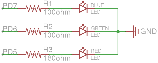
Figure 1: Schematic diagram for the LED connections.
|
| |
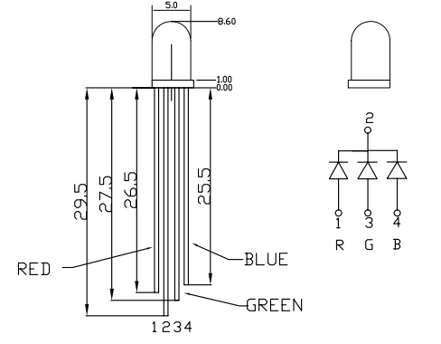
Figure 2: RGB Common Cathode LED (YSL-R596CR3G4B5W-F12).
|
For this section, you will be using a tri-color RGB LED. On the
breadboard, implement the circuit defined by the schematic in
Figure 1, but do not connect it to the Arduino yet. You
should refer to Figure 2 to determine the pin-to-color
mapping of the LED.
Checkoff: Once you have completed wiring on the breadboard, have the
instructor verify the connections before moving onto the next section.
Now connect the circuit on your breadboard to the proper pins on your
Arduino. The pins (PD5, PD6, PD7) are given in terms of the pin names
on the Atmel, you will need to determine the correct correspondence to
the output pins on the Arduino itself by refering to the Arduino
schematic. Write the code1 for your Arduino to turn on and off
each of these LEDs2. Does the LED turn on when the output pin is high or low?
For ease of use, you may want to define variable or macros that lets
you turn on/off a particular color LED by name instead of pin number.
Checkoff: Write code that cycles through the pattern
R,RG,G,GB,B,RB,ALL_OFF3 whenever the button is pressed. Show your completed program to an
instructor for checkoff. I suggest that you put all of the code for
this question in single function that you continually call from the
loop function. That way you can easily comment it out when you work
on the next part of this lab, without having to delete any code.
4 Fun with Arduino Libraries
4.1 Photoresistor
In your kit you have a photoresistor. This changes resistance based on
the amount of incident light. In order to use this you should connect it in a voltage divider configuration as shown in Figure 3.
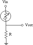
Figure 3: Schematic diagram for the photoresistor connections.
Connect the Vin to 5V and connect Vout to pin A0 on the Arduino. You can then use val = analogRead(A0) to read the voltage at Vout as scaled between 0 and 1023 (it is a 10 bit value). Print the value out over serial terminal and find a good resistor value to get a large change between having the photoresistor covered versus in bright light.
Checkoff: What value resistor did you use and what range did you find? Did the value go up or down when you covered it?
Checkoff: Given that the min value from analogRead is 0 and the max is 1023, what is the resistance of the photoresistor when covered? When not covered?
4.2 Servos
Servos are also controlled by PWM signals, which we will learn a lot
more about later in the semester. But for now, read the following
description and try to make the continuous rotation servo in your lab
kit work. Make sure to read through this section before trying to hook anything up or writing code.
Most servos enable angular
control of the output shaft (e.g. between 0 and 120 degrees). The
servos we are using in class are known as continuous rotation servos.
Instead of controlling position, we are able to control the forward
and backward rotational speed using PWM signals. Most servos use PWM
signals with a period of approximately 20 milliseconds. By varying
the pulse length between 1ms to 2ms the servo will go from full speed
forward to full speed backwards (on a traditional servo this would
mean rotating from 0 to 120 degrees).
Later in the class we will manually configure the PWM channels to control
the frequency and duty cycle. Right now, however, we will instead make use of an
Arduino servo control library. Read the information on how to use the
servo library here:
http://arduino.cc/en/Reference/Servo
To hook up the servos to your breadboard, you will need to first use
the 3-pin header to adapt the female servo connector to a male
connector. Then, connect the black wire to ground, red to power (5V),
and white to the PWM signal. Double check these connections before
powering your board. You can then add the wheel to the servo to more easily see what is happening. Note that the servos can draw more power
than a USB port can supply, especially if you try to hold the wheel.
Checkoff: Write code that reverses the direction of one servo whenever the button is pressed. If you have trouble with this please ask for help!
4.3 Combining Servos and Photoresistors
For this section you can place the breadboard with the photoresistor on top of the wheel on the servo to get it to move as the servo moves.
Checkoff: Use two photoresistors and write a program that will cause the servo to point to and follow the brightest source of light.
Checkoff: Now write a program that will point to and follow the brightest source of light using only a single photoresistor (this is more difficult and may bounce back and forth between locations).
Footnotes:
1 Y o u c a n u s e t h e A r d u i n o p i n
f u n c t i o n s o r d i r e c t l y s e t r e g i s t e r s f o r t h i s l a b . I s u g g e s t u s i n g
t h e A r d u i n o f u n c t i o n s i n i t i a l l y , b u t i f y o u h a v e t i m e y o u s h o u l d
m o d i f y t h e m t o d i r e c t l y s e t t h e r e g i s t e r s ( f o r t h e n e x t h o m e w o r k y o u
w i l l n e e d t o d i r e c t l y s e t r e g i s t e r s f o r s o m e q u e s t i o n s ) . T o s e t t h e
r e g i s t e r s d i r e c t l y , y o u s h o u l d p u t ` ` # i n c l u d e < a v r / i o . h > ' ' ( w i t h o u t
q u o t e s ) a t t h e t o p o f y o u r f i l e t o g e t a l l o f t h e r e g i s t e r
d e f i n i t i o n s ( D D R D , P O R T D , e t c ) .
2 Y o u s h o u l d w o r k t o g e t h e r o n t h i s p r o g r a m ,
e a c h g r o u p o n l y n e e d s o n e c o p y ; h o w e v e r , y o u s h o u l d m a k e s u r e t o
s h a r e t h e f i n a l v e r s i o n o f t h e c o d e a m o n g t h e m e m b e r s o f y o u r
g r o u p .
3 R G , f o r i n s t a n c e , m e a n s t h e r e d a n d g r e e n L E D s h o u l d
b e o n a t t h e s a m e t i m e .
File translated from
TEX
by
TTH,
version 4.03.
On 26 Jan 2016, 13:09.