CSCE 439/839: Robotics
Lab 2: PID, Range Finders, and Mapping
Instructor: Carrick Detweiler
carrick _at_ cse.unl.edu
University of Nebraska-Lincoln
Fall 2015
Started: Friday, September 25, 2015
Lab 2 Checkpoint (Up through Sec.
2.1): Friday, October 2, 2015
Lab 2 Due Date: Friday, October 16, 2015
1 Overview
In this lab you will implement a PID controller to control the angle
of your fanboat. You will also attach range sensors, characterize them, and then implement a variety of
algorithms that utilize the range finders. Make sure to read through
the entire lab before starting to implement these controllers. You
should also map out the final architecture of your ROS nodes with your
group before you begin implementing these. Figure 1 shows one possible configuration.
You are expected to complete up to and including
Section 2.1 for the checkpoint; however, I would encourage you to have completed more than this by the time of the checkpoint.
Remember and review the safety instructions from Lab 1.
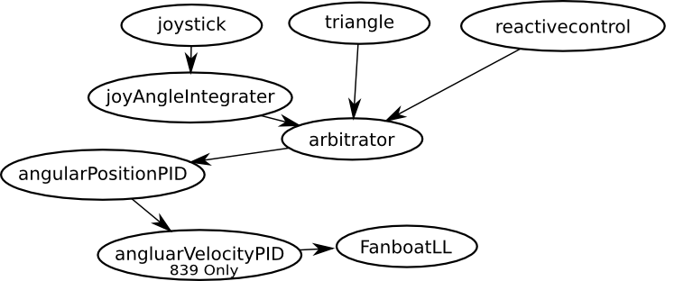
Figure 1: Overview of possible node configuration.
2 PID (30 pts.)
In the previous lab you implemented control of the fanboat using
the remote control. You had no
way to specify a particular angle to go to (you had to manually
control it).
In this section of the lab, you will implement a
Proportional-Integral-Derivative (PID) controller to control angular
position. Below I describe a general PID controller, you can also
read more about PID control on the wikipedia page:
http://en.wikipedia.org/wiki/PID_controller.
We will also covered this topic in class.
You should create a new ROS node for PID control of position.
You could call it angularPositionPID or something similar.
You should make this node such that you can insert it between your joystick control node and the node that sends commands to the fanboat. That way you will be able to easily configure your system to run either the joystick doing direct control or with the PID just by modifying the launch file. Look into the remap keyword for the launch file in order to do this quickly and easily.
Question: Describe what remap does and how you used it.
For groups with majority of 839 students only (this paragraph): you should also implement a PID controller to
control the angular velocity of the fanboat. This should sit
between the angular position controller and the FanboatLL node.
Start by implementing this node that controls the velocity before
implementing the position PID. You should perform experiments and
answer questions for both PID controllers.
Here is a brief summary of PID control as we discussed in class. You should make sure to read
this whole section before starting as some of the work for the later
questions will be helpful in answering the earlier ones. If you have
a target angle at and a current angle (as read by
your IMU) of ai, then you can control the rotational thrust, r,
of your fanboat according to:
r = P(a_t-a_i)
P is the proportional scaling term of the controller (and can be
positive or negative). With a P controller, if you are far off from
your target angle, it will have high thrust and when it gets closer
the thrust will decrease. This can work well, but if P is too low
it will never reach the target and if it is too high, it will
overshoot and oscillate.
By introducing a derivative, D, term oscillations can be damped:
r = P(a_t-a_i) + D(e_i-e_i-1)
where ei is the error from this time step, at−ai, and
ei−1 is the angle error, at−1−ai−1, from the previous time
step and D is the derivative scaling term of the controller. The
value (ei−ei−1) is basically a numeric derivative of the error
and it tends to slow how fast the output term r will change (damps
oscillations).
A purely PD controller often works well and I recommend that you first
try a PD controller before trying to introduce an integral, I, term.
The problem is that a PD controller will not always achieve the set
point 1. Adding
an integral term can ensure that you reach your target, but at the
cost of potentially adding oscillations and having to deal with issues
such as windup. Adding the I component will yield:
r = P(a_t-a_i) +I(integral_i) + D(e_i-e_i-1)
where, integrali = integrali−1 + (at−ai), and integral0 = 0. The windup problem is that if there is an offset (e.g. you hold
your fanboat in one position and don't let it rotate for a while),
then the integral term will continue to grow unbounded. So typically,
you need to bound the integral term by a maximum value to mitigate
this problem.
In essence, a PID controller is not too difficult, however, there are
a number of practical issues that you must address when using one.
The first, is tuning the PID values (see Section 2.1 on
setting parameters, which you may want to complete before this
section). Wikipedia has a number of suggestions as to how to tune the
controller. My preferred method is to first try a PD controller
(almost always works better than a purely P controller). The idea is
that you first set D=I=0 and then tune P until it oscillates
slightly, then add D until the oscillations are damped. On the
fanboat, the I term probably isn't needed, but if you find that
there is an offset from the final position, then you can add a little
bit of I to make sure it achieves the target.
Question: Did you need to use an I term? What were your final
values for the PID parameters? What are the units of the parameters? (839: answer for velocity controller as well)
There are a number of other practical issues when controlling
rotational systems by degrees. For instance, when doing more than a single rotation, there will be a discontinuity in the angle measurement.
Question: How did you deal with the discontinuity between the angle measurements if you do multiple full rotations?
Another issue with a PID controller is timing. The gain parameters
will depend on the frequency at which you update the commands. In
your PID controller, you will need to subscribe to and receive both
the angle target message as well as the current gyro position message.
You should base your main PID control loop on the rate at which you
receive the current gyro position. The reason to do this is because
the rate that you receive this message is relatively constant, whereas
you will likely receive angle target messages at an irregular rate.
Also, by using this approach, the fanboat will also maintain the
target angle when it is sitting still or while it is translating.
Question: A final issue you need to address is making sure that the
PID controller never exceeds the maximum rotational rate the gyro can
handle. How did you address this problem?
Your fanboat joystick node should use the PID control node. To do
this, you should reconfigure your joystick node to send messages to
the PID node. However, since the PID node takes a target angle as
input, you will need to change your joystick node so that it outputs a
target angle, instead of an angular rate. There are a couple of ways
you can do this. The first approach is to integrate the yaw control
input in your fanboat joystick node to produce an absolute target
angle. The other approach is to create a new node that takes the
output of the fanboat joystick node and integrates the angular rate
command into an absolute angle command before passing the target angle
onto the PID controller. You should do the latter to allow easy removal of the PID node as discussed above, but there are still a number of ways you can structure it.
Regardless of how you structure the system, you should integrate the
joystick yaw commands at a fixed rate (and not just every time you get
a joy message as these are irregular). To do this, you will need to
use a ROS timer (although there are other ways as well). You can find details at
http://www.ros.org/wiki/roscpp/Overview/Timers. Here are the
basic commands you need to use to create a timer:
//Define the timer as a global member of your class
ros::Timer timer;
//Create the timer to run at 10Hz, assuming your node is named joyControl
timer = nt.createTimer(ros::Duration(0.1), &JoyControl::updateSetpoints, this );
//The callback function called at 10Hz
void JoyControl::updateSetpoints(const ros::TimerEvent& e){
   //Integrate your readings and publish messages
}
In essence, this will make your joystick control the speed that the
fanboat rotates. You should scale the frequency of the update and
potentially add a scaling factor to the integration so that moving the
stick all the way in one direction will correspond to the maximum
rotational rate you can achieve.
Question: If you manually prevent the fanboat from rotating, the
integration will continue. When you let go, it will spin rapidly to
"catch up," even if you have already let go of the joystick. This
isn't very nice behavior. Correct this behavior so that it will
always "respect" the joystick command (e.g. if the joystick is
centered it should not be rotating and if it is half way it should be
spinning at half speed even if you manually stop it and then release
it). How did you correct this2?
In addition to having the joystick control the rotational rate, make
one of the buttons on your joystick rotate the fanboat by 90
degrees. This will be useful as a method to test the performance and
stability of your PID controller.
Question: Plot outputs of your current angle, target, and rotation
thrust levels for different PID values when changing the target angle.
Do this both for changing the target angle with the joystick and also
with the 90 degree rotations with the joystick button. Make sure to
include an output from your final PID controller. Also include plots
from a purely P controller when it has a value that causes oscillation
and when it does not cause oscillation. Include any other plots that
you find useful. (839: answer for velocity controller as well both when giving position commands and when directly giving velocity commands)
2.1 ROS Parameters
When you
are developing your PID controller, it is convenient to be able to set
the PID values from the launch file so that you do not need to
recompile your code each time you want to change the
parameter3. Look at the website
http://www.ros.org/wiki/roscpp/Overview/Parameter\%20Server to
see how to read/set parameters.
In general, to read a parameters in C++ you should do:
  P = 1.0;
  nh.param("rCtrl/P",P,P);
  I = 0.0;
  nh.param("rCtrl/I",I,I);
  D = 0.0;
  nh.param("rCtrl/D",D,D);
This will set default values (in case none are specified in the launch
file), but use the value from the parameter server if any are present.
The launch file should then have:
  <param name="rCtrl/P" type="double" value="1.0"/>
  <param name="rCtrl/I" type="double" value="0.0"/>
  <param name="rCtrl/D" type="double" value="2.0"/>
to set the parameters.
Question: What command-line command can you use to get the values of
these parameters? What about setting them? What happens if you set
them on the command line, do the values the program is using change?
What about if you change them using the command line and then relaunch
your launch file? If you relaunch your node using rosrun?
What does this tell you about the order/priority of the various ways
you can set parameters?
2.2 Arbitrators and Triangles
Up until now, you have primarily controlled your fanboat using the
joystick controller. Now we will add the ability to control the
fanboat autonomously. Our first autonomous controller will be a
dead-reckoning "triangle" driving controller. Before we do this,
however, you will need to create a new ROS node that is an arbitrator
for the commands being sent to your PID controller. This node should
subscribe to two different message types. The first should be the control message that will be passed onto the PID controller if that state is selected.
The other message this node subscribes to is a state message, which
should allow selection of which message
should be passed onto the PID controller.
Question: Describe the structure of your arbitrator and how it works
and interacts with other nodes.
Now implement a new node that drives the fanboat in a triangle.
You can do this by using a series of 120 degree turns followed by a
period of constant forward thrust. Make the arbitrator use this node
when one of the buttons on your controller is pressed. Make this node
really simple. Do not subscribe to the joy message. Instead, this
node should always be sending out triangular trajectories (it may need
to subscribe to the gyro angle to know what the target rotational
angle should be). The arbitrator will handle deciding which node to
pay attention to.
Question: Describe the operation and structure of your triangle
trajectory node. Also comment on the performance and how well it
actually drives a triangle. Include any useful plots (e.g. the gyro
angle as it travels and the thruster outputs).
3 IR Rangers and Reactive Control (25 pts.)
In section you will augment your fanbaot with two IR range finders.
You will characterize the sensors and then develop some basic reactive
controllers and also a basic mapping system.
3.1 IR Range Finder
Each group has two IR range finders. These are made by Sharp and the
model number is GP2Y0A02YK0F. It is a 5V sensor that outputs
an analog voltage. It can sense ranges roughly between 15cm and
150cm. You can find a datasheet and more information on the sensor
here: http://www.sparkfun.com/products/8958. The first thing
you need to do is create and solder connectors to connect the sensor
to your fanboat. These should plug into ports "AX" ports on your IMU as discussed in lab. If you are uncertain how these
should be connected, please ask the instructor.
You can quickly see if the sensor is operating properly by looking at
the ADC reading messages that the FanboatLL node produces.
Verify that you are obtaining reasonable readings by echoing the ADC
messages.
Next, mount the range finders to your fanboat. Where you locate
them is up to you (and you may decide to change it in the future).
Make sure to read through the rest of the lab and decide on reasonable
locations to accomplish the tasks in this lab. Note that if they are
too close together they may interfere. Also, be aware that if
multiple fanboats are operating in the same area you may get some
interference from the other robots.
Question: Where did you end up mounting your IR range finders? Why
did you put them in these locations? Include a picture of the final
configuration.
The next step is to convert these raw ADC readings into ranges. I would suggest that you create a new ROS node that subscribes to the
ADC message and publishes two different range messages. The
datasheet has a graph indicating the conversion between range and
voltage. However, this may not be completely accurate for your sensor
and you will also need this information in your ROS node to convert
between voltage and distance.
Question: Do an experiment to characterize the voltage-to-range
conversion of your sensor. Report on your results and include a plot
showing the response.
Question: Do some experiments to characterize the smallest objects
that the IR range finder can find at various distances and report on
the results.
Question: Experimentally determine the beam width of the IR sensor and
report on how you determined this and the results.
3.2 Reactive Control
Your next task is to develop a reactive controller that tries to
maintain a fixed distance from an obstacle in front of your
fanboat. To do this, create a new ROS node that subscribes to the
range messages and publishes control commands to the arbitrator node.
In your joystick node, make it so you can activate the reactive
control by pressing one of the buttons.
There are a number of approaches you can use to try to maintain a
fixed distance from an object. You can use thresholds and fixed
thrusts, a PID controller, or other methods. The key challenge will be
stopping before you get too close and minimizing overshoot while still being reactive enough when the object moves away.
You should test your
controller by moving something (e.g. a book) further away
from the fanboat to see that it tracks it. Since your PID
controller is still running, the fanboat should maintain the same
angle while it is doing this, although it may drift in translation.
Question: How did you implement distance control? How well does it
work? Include a plot of the distances obtained from the range finders
as well as directional control outputs as you move an object around in
front of the fanboat.
Since you have two range finders, you can also implement a behavior
where the fanboat will turn to keep an object in front of it in
addition to maintaining a fixed distance. While not required for this
lab, you may be inspired to implement this behavior. If you do,
report on it as well.
4 Mapping (20 pts.)
Your next task is to use the fanboat and range finders to create a
rough "map" of the environment. If your fanboat tends to
translate significantly while rotating, now would be a good time to
try and calibrate it so that it can mostly rotate in place.
As in the previous sections, create a new ROS node that publishes to
your arbitrator and make a button on your joystick control the
arbitrator. One difference from the previous nodes is that this node
probably needs some knowledge about when it should start the mapping.
You can do this by subscribing to the state topic, joy topic (not
recommended), or having your joystick control node publish a message
to this node.
In order to map, you should rotate slowly and collect and store range
finder information. After you have completed the rotation you will
have a set of ranges to everything around your robot.
Then implement the following behavior. After mapping your local environment, your robot
should move towards the closest point it finds (or perhaps cluster of
points if you find that there is noise in the sensor readings). Once
it starts moving towards the closest point, you should switch to the
reactive control mode you developed in Section 3.2. If
it loses sight of the object it should perform the search again. With
this behavior, your robot should be able to follow you around (slowly)
as long as you are the closest object to it.
Question: Describe how you implemented this simple mapping function.
Question: What speed does your robot rotate at? Why did you choose
this speed?
Question: How did you implement the changing of states? Hint: you may
want to implement another node that manages the states, although this
is not necessary.
Now implement the opposite behavior where the fanboat moves towards the location with obstacles that are furthest away. Then move in that direction until an obstacle is detected and then repeat the behavior. You should make sure that you do not try to drive through small gaps that are too small for your vehicle.
Question: Describe this implementation and conduct experiments with it to determine how well it works.
5 To Hand In
You should designate one person from your group as the point person
for this lab (each person needs to do this at least once over the
semester). This person is responsible for organizing and handing in
the report, but everyone must contribute to writing the text. You
should list all group members and indicate who was the point person on
this lab. Your lab should be submitted by handin, http://cse.unl.edu/~cse439/handin/, before the start of
class on the due date. Include a pdf of your report and your source code in handin. Also make sure to bring in a printed copy to class on the due date.
Your lab report should have an introduction and conclusion and address
the various questions (highlighted as Question: ) throughout the lab in
detail. It should be well written and have a logical flow. Including
pictures, charts, and graphs may be useful in explaining the results.
There is no set page limit, but you should make sure to answer
questions in detail and explain how you arrived at your decisions.
You are also welcome to add additional insights and material to the
lab beyond answering the required questions. The clarity,
organization, grammar, and completeness of the report is worth 10
points of your lab report grade.
In addition to your lab report, you will demonstrate your system and
what you accomplished up to this point to the instructor at the
beginning of lab on the due date. This is worth 15 points of
your overall lab grade. You do not need to prepare a formal
presentation, however, you should plan to discuss and demonstrate what
you learned and accomplished in all sections of the lab. This
presentation should take around 10 minutes.
Question: Please include your code with the lab report. Note that you
will receive deductions if your code is not reasonably well commented.
You should comment the code as you write it, do not leave writing
comments until the end.
Question: Include an rqt_plot of your final system and comment
on your overall system architecture.
Question: For everyone in your group how many hours did each person
spend on this part and the lab in total? Did you divide the work, if
so how? Work on everything together? Give details on the hours each group member worked (e.g. keep a list of how many hours per day each person worked and on what).
Question: Please discuss and highlight any areas of this lab that you
found unclear or difficult.
Footnotes:
1 T h i n k o f a P D c o n t r o l l e r a s p u l l i n g a c a r u p a h i l l
w i t h a s p r i n g , n o m a t t e r h o w s t i f f t h e s p r i n g , i f y o u p u t o n e e n d
w h e r e y o u w a n t t h e c a r t o e n d u p , i t w i l l n e v e r g e t t h e r e .
2 O n e a p p r o a c h i s t o d o P I D
c o n t r o l o n v e l o c i t y i n s t e a d o f p o s i t i o n , b u t f o r t h i s l a b , k e e p y o u r
P I D c o n t r o l l e r i n t e r m s o f a n g l e , n o t v e l o c i t y
3 I n a d d i t i o n t o b e i n g a b l e t o s e t P I D v a l u e s i n t h e
l a u n c h f i l e , y o u m a y w a n t t o c r e a t e a m e s s a g e t h a t a l l o w s y o u t o
a d j u s t t h e P I D v a l u e s w i t h o u t h a v i n g t o r e l a u n c h t h e n o d e . B u t e v e n
i f y o u d o t h i s , y o u s h o u l d a l s o b e a b l e t o s e t d e f a u l t p a r a m e t e r s i n
t h e l a u n c h f i l e .
File translated from
TEX
by
TTH,
version 4.03.
On 25 Sep 2015, 08:56.