CSCE 436/836: Embedded Systems
Lab 1b: Hoverboard Programming Introduction


Instructor: Carrick Detweiler
carrick _at_ cse.unl.edu
University of Nebraska-Lincoln
Spring 2011

Started: Jan 27, 2011
Lab 1 (parts A and B) Due: Feb 3, 2011

1  Overview

This is the second part (b) of Lab 1. In this part of the lab you will learn the basics of writing code for and programming the hoverboard. The hoverboard is the embedded system that we will use in this course to control the hovercraft we are building. You won't get to the point of controlling the hovercraft motors in this lab, but that will come soon.
In this lab, you will learn how to control LEDs and respond to button presses. This will require using the skills you learned in class in identifying components in the hoverboard schematic, reading datahseets, and programming in C.

2  Materials

You will not need to use the hovercraft base you built in part (a) of this lab. The main items you will be using in this lab are:
Your team is responsible for returning the hoverboard and netbook computer assigned to your group in working condition at the end of the semester. Please treat them well. Locks have been provided for the netbooks so that you can leave them locked in the lab when you are not present. Report any problems, damage, loss, or theft of any lab items immediately.

3  Safety

Please be extremely careful with the hoverboard. Make sure that you keep any metallic objects far away from the hoverboard. This includes rings, necklaces, coins, pens, etc. Also, never place the hoverboard on anything conductive as there are exposed elements on the back of the hoverboard. You should also never have liquids near the hoverboard. Be careful when connected cables and wires to the hoverboard to make sure that you connect it to the right port and in the right orientation.
To help prevent some problems, use electrical tape to cover the bottom of the hover board. This will help prevent some accidental shorts.
We will be using high-power, two cell Lithium-Polymer (LiPo) batteries to power the hoverboard. Please be extremely careful with these batteries and recall the safety information we discussed in class and lab. In particular, only use the designated chargers in the lab to charge the batteries. The hoverboards will not turn on if the voltage on the battery is too low, however, you should also be aware of the use of your battery and never leave it connected to the hoverboard when not in use. A fully charged battery will have a voltage of 8.4V. A battery that is about half charged will have a voltage of approximately 7.4V, and a nearly discharged battery will have a voltage of around 7.0V. A voltage below 6.0V can be dangerous, especially if you try to recharge it. If this happens, please let the instructor know immediately. With care, it is possible to revive an over discharged battery if it is done quickly (but putting it on the charger is not the way to do it and it is dangerous).
Unlike programming a normal computer, it is possible that a bug in your code could physically damage the hoverboard or other devices. Take care, especially when programming I/O pins as setting the wrong state on the wrong pin could damage the processor or peripherals.

4  Hoverboard Overview

The schematic for the hoverboard is available online on the course website. Familiarize yourself with the schematic as you will be using this extensively. Recall that the hoverboard has two ATMega1284p processors. One runs at 5V and the other runs at 3.3V. These are named ATMEGA_5 and ATMEGA_3.3, respectively, on the schematic. For the moment we will be focusing on using the 3.3V processor as this is the one that controls the motors.
Question: What page in the schematic is the 3.3V processor on?
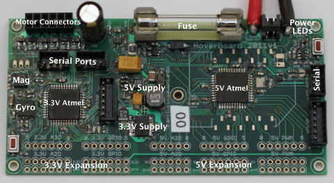
figures/board_pic/board_pic.jpg
Figure 1: A picture of the hoverboard electronics
Figure 1 shows a picture of the hoverboard. The main components of the board are labeled. The left side of the board contains the 3.3V processor and all of the 3.3V sensors and peripherals, while the right side has the 5V processor and peripherals. The bottom edge of the board contains a number of expansion ports that can be used to add sensors and servos to the hoverboard. Again, those on the left side are 3.3V, while on the right side they are 5V.
At the top left of the board, next to the large capacitor, there are 0.1 inch headers that allow connection of the motors.
Question: If you connected a motor to the hoverboard, would the black (ground) wire of the motor be towards the top or bottom of the hoverboard? Note, do not connect any motors in this lab.
At the top of the board, near the center, is a large fuse. This fuse is largely intended to protect the battery from shorts, not the board. This is because the normal operating current for running a couple of motors (5 to 10 amps) is more than enough to burn most things on the board. However, if the power indicator LEDs do not turn on, it is possible that you have blown your fuse (by shorting something or running too many motors at once). Contact the instructor if this occurs.
To the right of the fuse is the power cables and then a set of three power indicator leds. The green LED will be on if power is connected and the battery voltage is good. The yellow and green light will both be on if the battery voltage is below 7.0V. The red and yellow LED turn on, if the battery voltage drops below 6.6V. When the yellow light turns on steadily, it is time to charge your battery. If the red LED is on, the power to the rest of the components on the board is disabled to help prevent the battery from over discharge. If the red LED turns on, you should replace your battery immediately. Note that when the motors are running the yellow and/or red LED may flicker as the resistance in the wires and battery cause a drop in voltage. This is ok, when the red LED starts to be on fairly steadily with the motors on, it is probably time to replace the battery.

5  Programming the Hoverboard

We will use the netbook computers to compile code and program the Hoverboard. Most of the needed utilities are pre-installed. However, you should verify this by running through the computer setup section. You can also use this to install the needed software on your own computer. The instructions are for Ubuntu, although it is possible to set this up on most GNU/Linux platforms and possibly on OS X (it is much more challenging on Windows). You can also use setup Ubuntu on a virtual machine (VMWare, VirtualBox, etc.) if you run Windows or OS X.

5.1  Computer Setup

It is important to note that none of the data on the netbooks are backed up. You should make sure that you keep copies of your code and anything else on the computer elsewhere. The best option is to setup a source control repository for your code. While this is the recommended option, it is not required for this lab. You can also use a usb stick, space on CSE or UNL shared drives, or other services like Dropbox to backup your code. If your drive crashes it is not an excuse to turn in the lab or assignment late. No extensions will be granted. If this happens, I will hand you an different machine and expect you to complete the assignment on time.
Use the account name and password given to you for your computer. Please change the password to something your group will remember. We will use the following packages in this course: gcc-avr, avr-libc, subversion, mercurial, scons, avrdude. To install them, you can use the graphical package manager, or on the terminal you can type:
sudo apt-get install gcc-avr avr-libc subversion mercurial scons avrdude

In this course we will be editing C code. You can edit code in the editor of your choice. You might try gedit, emacs, vi, eclipse, or something else. We will compile and program the hoverboard using the command line. You should familiarize yourself with the command line if you have not used it previously (google for more info or look at https://help.ubuntu.com/community/UsingTheTerminal).

5.2  Compiling Code

We will be using SCons to compile the source code. SCons automates the build process and is similar to Make but is more flexible and integrates configuration functionality like autoconf (don't worry if you don't know anything about make and autoconf). SCons an open source program written in python. Customizing build scripts is easy as they are written in python. SCons is used by a variety of well known projects, including Google Chrome and VMware.
To compile code for the hoverboard, make sure you have the sample code which is available on the assignment page of the course website. The sample code provides a template for the code we will be writing in this lab and also has the needed build scripts. The sample code should compile as it is. Try compiling it before modifying the code. To compile the code, simply type scons in the code directory from the command line. There should not be any errors or warnings.
If you add any new source files (.c) you can tell SCons to compile those as well by editing the SConstruct file and adding it to the list of sources at the top of the file.

5.3  Loading Code

To load/program the code on the hoverboard we will use the program avrdude. First, connect the usb to serial port to the computer and uart port AT3_UART0 on the hoverboard. This is located slightly above and to the right of the 3.3V Atmel processor. I have provided a programming script to automate programming the board. To program the board, execute the command (from the command line, while in the code directory):
./program

right after you press the reset button for the processor. You only have a few seconds after you reset the board to program the processor. This is because there is a bootloader that starts after reset and waits for commands over the serial port for a short time before launching the main program. The red light on the board will blink a few times before the main program launches. You will know that the board is programming by the output on your terminal and the green light on the board will turn on.

6  LEDs and Buttons

In this section you will program the hoverboard to control the LEDs and button on the 3.3V Atmel. Make sure you downloaded the sample code from the course website and that you are able to compile and program the hoverboard with this code before you start writing your own code. You should look over all of the files and look for sections labeled STUDENT CODE for sections that you need to fill in, although, for this first section the only code you are provided is an empty main function and while loop.

6.1  LEDs

Examine the schematic and determine which pins on the 3.3V Atmel control the two LEDs. The pins are labeled with their various functions. We are interested in using the pins as general digital input/output (I/O) pins. In the schematic take note of what port and pin number the LEDs are connected to (for instance, PB3 which would correspond to pin 3 on port B, which is NOT the port the LED is on).
Question: What are the ports and pins that the LEDs are connected to?
Write code to initialize and turn on and off the LEDs. You will need to refer to the ATMega1284p datasheet (located on the course website) to determine the correct registers to set to control the LEDs. Look for STUDENT CODE sections in the code to determine where to start writing your code. You are encouraged, however, to also create and add functions or new files to organize you code. In particular, I would recommend creating led.c and led.h files that contain functions related to controlling the LEDs.
To start out, you should try just turning on both LEDs. The next step is to alternate turning on one and then the other. You will probably need to create a delay function to create a long enough delay between turning on and off the LED. You can do this with a busy wait for loop. Note that you may need to insert a asm volatile(``NOP'') into your for loop to prevent the compiler for optimizing out your empty loop (this is an assembly instruction that just tells the processor to do nothing for a cycle).
Question: What do the LEDs do if you just alternate turning on and off an LED without any delay?
Experiment with different methods for delaying and calibrate your code so that you can delay a specific amount of time (for example milliseconds or seconds). Try using different types (e.g. uint8_t and uint32_t) for the counters in your loops. You may need to nest loops with the uint8_t type as you can't count very high with this type.
Question: The processor runs at 8MHz. How many iterations of your busy wait loop do you need to run to delay for a second? How many assembly instructions does this mean the processor is executing for each iteration of the loop? How does this change when you change the type of your counter?

6.2  Buttons

Now we are going to use the button as an input to the processor.
Question: What processor pin reads the button?
We will use the LEDs to give us feedback about the state of the button. Write code to have one LED on when the button is pressed and the other LED on when the button is not pressed.
Question: Try this out, does it work as expected?
Now look at the button on the schematic. When pressed, the button connects the processor pin to ground through a 1k resistor. The state of the pin, however, may not be defined beforehand. In this case the pin is said to be "floating." This means it could be high or low at any given time. If you were lucky the button worked as expected, but this may not be the case. To make sure that the button works correctly, enable the internal pull-up resistor1 on the button reading pin.
Question: What code did you write to enable the pull-up and read the pin?
Now do something more interesting when you press the button. For instance, make it blink twice in a row with every button press.
Question: What happens if you press the button multiple times before it is done blinking? How could you change your code so that it acts correctly (you don't actually have to implement this, but feel free to)? This is somewhat challenging and messy without the use if interrupts or timers, which we will learn about later in the course.
Question: For this section make sure to hand in copies of the code you wrote.

7  Fun With Morse Code

I have provided the basic code to enable Morse Code blinking of the LEDs. Don't worry, you won't need to learn Morse Code, this would be a horrible way to debug.

7.1  Short and Long Blinks

Using the LED functions you previously wrote, fill in the code to perform long and short blinks (morseLongBlink() and morseShortBlink()). You also need to fill in the code that provides pauses between symbols, morseShortPause(), and a longer pause for between characters, morseLongPause().

7.2  Hello World

Fill in the code for morseBlinkString() which takes a string and outputs the correct sequence of blinks for that string. You can make use of morseBlinkChar to aid you. Have your board blink "hello world" when it starts up!

7.3  Button Presses

Now write code that will output "hello" on one LED if you press the button once and "world" on the second LED if you press the button twice in a row.
Question: This is not completely trivial. Describe your approach and make sure to hand in the code with the lab.

7.4  Optional: Extend Morse Code Library

As an optional assignment, you can extend the Morse code library to handle numbers and punctuation. Adding numbers isn't too hard as they all have just 5 symbols. Some punctuation requires six symbols, which may involve increasing the size of the morseTable array to 16 bit stored values instead of 8, although there may be a clever way around this.

7.5  Optional: Read Morse Code Input

As an optional assignment, you can extend your button pressing reading code to include reading Morse Code input. The challenge here is that different people will input different length dots and dashes, so you will need some sort of online calibration (or just fix it to a small range).

8  To Hand In

You should designate one person from your group as the point person for this lab (each person needs to do this at least once over the semester). This person is responsible for organizing and handing in the report, but everyone must contribute to writing the text. You should list all group members and indicate who was the point person on this lab. Your lab should be submitted by email before the start of class on the due date. A pdf formatted document is preferred.
Your lab report should have an introduction and conclusion and address the various questions (highlighted as Question: ) throughout the lab in detail. It should be well written and have a logical flow. Including pictures, charts, and graphs may be useful in explaining the results. There is no set page limit, but you should make sure to answer questions in detail and explain how you arrived at your decisions. You are also welcome to add additional insights and material to the lab beyond answering the required questions.
N.B. This is part (b) of Lab 1. You should complete a single lab report for all of Lab 1.
Question: Please include your code with the lab report. Note that you will receive deductions if your code is not reasonably well commented. You should comment the code as you write it, do not leave writing comments until the end. I recommend structuring your code such that for every section of this lab, a different function is called from the main loop. Then you will be able to comment out just one function to change between sections in the lab and you won't have to delete working code from previous parts of the lab.
Question: For everyone in your group how many hours did each person spend on this part and the lab in total? Did you divide the work, if so how? Work on everything together?
Question: Please discuss and highlight any areas of this lab that you found unclear or difficult.

Footnotes:

1Not all processors have configurable internal pull-up resistors, this is one of the nice features of this Atmel processor


File translated from TEX by TTH, version 3.89.
On 27 Jan 2011, 09:50.