CSCE 436/836: Embedded Systems
Lab 1a: Hovercraft Construction and Experiments
Instructor: Carrick Detweiler
carrick _at_ cse.unl.edu
University of Nebraska-Lincoln
Spring 2011
Started: Jan 20, 2011
Lab 1 Due: Feb 3, 2011
Lab 1a Recommended Completion Date: Jan 27, 2011
1 Overview
This is the first part (a) of Lab 1. In this lab you will design,
construct, and perform experiments with the physical hovercraft. In
the second part (b) of this lab, you will learn to program the
hoverboard embedded system that we will use to control the hovercraft.
In future labs we will use the information you collect to calibrate
controllers you will develop on the hoverboard embedded system.
Before starting you should read through the whole lab. Some parts can
be done in parallel, while some sections rely on the completion of
previous sections. You should discuss your plan of attack for the lab
in your group and decide how you will work together and divide the
work. Everyone, however, is responsible for knowing about all
sections of the lab.
2 Materials
The main materials you will use in this part of the lab to construct
the hovercraft are:
- Sheet of 1.5 inch think rigid foam insulation
- 5mil plastic sheet
- Six GW/EDF40 Ducted Fans (thrusters)
- Wire, tape, brackets, screws, etc.
You will also use a various hand tools including knives, soldering
irons, power supplies, etc.
3 Safety
In this lab you will be using a number of tools and devices that can
be dangerous if mishandled. You should always follow instructions,
think twice, and ask for help if you are unsure what you are doing or
are unsure about safety. Please report any accidents to the course
staff and seek medical attention immediately if needed.
Reasonable precautions will prevent most accidents. Do not work in
the lab alone or when you are tired.
Throughout this course you will be using ducted fans for propulsion of
the hovercraft. These are relatively safe, but you should never put
your fingers or anything else inside of them. Along these lines, if
you have long hair, you should make sure to tie it back or cover it
while in the lab.
We will also be using power supplies and batteries in this course.
Make sure to follow instructions when using these devices as they can
be dangerous if misused. You should always be careful not to short
wires on batteries or power supplies and follow appropriate methods
for charging batteries.
Finally, in this lab you will be using sharp knives and soldering
irons. These can cut or burn you or your classmates. Always be aware
of your surroundings when using these devices and never cut towards
yourself or anyone else.
4 Hovercraft Design and Construction
In this section you will design and construct your hovercraft. The
exact configuration will be left up to you. The only constraint is
that the hovercraft must be omni-directional (able to translate in any
direction) and it must have rotational control (ideally equal control
clockwise and counterclockwise).
One of your goals in designing and constructing your hovercraft is to
make it look nicer than mine. This shouldn't be too hard :)
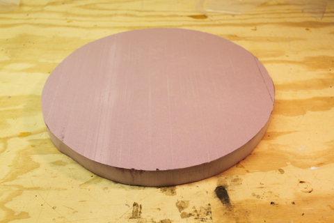 Figure 1: A foam circle cut out of the sheet of rigid foam.
For the base we will be using 1.5 inch rigid foam insulation. This is
a lightweight material that is easy to work with and relatively
inexpensive. There are a variety of circle templates that you can use
ranging from about 12 inches to 17 inches in diameter. You are free
to make your hovercraft whatever diameter you choose. The only
constraints are that it should be larger than 10 inches in diameter
and no more than 20 inches. You can also create other shapes,
although I suggest you cut a circle as it makes creating a good skirt
significantly easier.
To cut the foam, first lay your template circle on top of the foam.
Select a portion of the foam that will result in as little wasted foam
as possible. Trace a circle on the foam with a pen or marker. Remove
the template and then carefully cut the foam out using provided knife.
When using the knife extend the blade to a length slightly longer than
the width of the foam and then use the locking nut to lock the blade
in place. Make sure to keep the blade perpendicular the surface to
ensure a clean cut. Small sawing motions may be helpful. Note,
you should cut the foam over the plywood or off the edge of the
table so that you do not cut into the workbenches. Also, it may be
helpful to do a rough cut first (minimizing waste) so that you can
maneuver the piece of foam more easily.
Figure 1 shows the end result. Having a perfect
circle is not critical, but you should trim off any large errors. You
can always make a slightly smaller circle if you mess up the first
cut.
Question: What diameter hovercraft base did you decide to use? What was your reasoning?
Figure
Figure 2: A flexible walled skirt design. Air flows down into the skirt and inflates it. Most air remains inside and recirculates. A small amount of air leaks out and provides the air cushion (Image modified from original on wikipedia.org hovercraft entry).
The skirt is the most critical component of a hovercraft. There are
multiple types of skirts including bag skirts, wall skirts, and finger
skirts (roughly ranging from easiest to hardest to build). The goal
of all skirt designs is to provide a small cushion of air under the
hovercraft, while adapting and conforming to any irregularities in the
surface. If the surface were perfectly smooth (think about air-hockey
tables), you wouldn't need a skirt, you could just pump air under the
hovercraft and it would create a nice cushion. In practice most
surfaces are somewhat irregular, so the skirt needs to be flexible
enough to adapt to the surface, yet strong enough to hold in the air
pressure.
Figure 1: A foam circle cut out of the sheet of rigid foam.
For the base we will be using 1.5 inch rigid foam insulation. This is
a lightweight material that is easy to work with and relatively
inexpensive. There are a variety of circle templates that you can use
ranging from about 12 inches to 17 inches in diameter. You are free
to make your hovercraft whatever diameter you choose. The only
constraints are that it should be larger than 10 inches in diameter
and no more than 20 inches. You can also create other shapes,
although I suggest you cut a circle as it makes creating a good skirt
significantly easier.
To cut the foam, first lay your template circle on top of the foam.
Select a portion of the foam that will result in as little wasted foam
as possible. Trace a circle on the foam with a pen or marker. Remove
the template and then carefully cut the foam out using provided knife.
When using the knife extend the blade to a length slightly longer than
the width of the foam and then use the locking nut to lock the blade
in place. Make sure to keep the blade perpendicular the surface to
ensure a clean cut. Small sawing motions may be helpful. Note,
you should cut the foam over the plywood or off the edge of the
table so that you do not cut into the workbenches. Also, it may be
helpful to do a rough cut first (minimizing waste) so that you can
maneuver the piece of foam more easily.
Figure 1 shows the end result. Having a perfect
circle is not critical, but you should trim off any large errors. You
can always make a slightly smaller circle if you mess up the first
cut.
Question: What diameter hovercraft base did you decide to use? What was your reasoning?
Figure
Figure 2: A flexible walled skirt design. Air flows down into the skirt and inflates it. Most air remains inside and recirculates. A small amount of air leaks out and provides the air cushion (Image modified from original on wikipedia.org hovercraft entry).
The skirt is the most critical component of a hovercraft. There are
multiple types of skirts including bag skirts, wall skirts, and finger
skirts (roughly ranging from easiest to hardest to build). The goal
of all skirt designs is to provide a small cushion of air under the
hovercraft, while adapting and conforming to any irregularities in the
surface. If the surface were perfectly smooth (think about air-hockey
tables), you wouldn't need a skirt, you could just pump air under the
hovercraft and it would create a nice cushion. In practice most
surfaces are somewhat irregular, so the skirt needs to be flexible
enough to adapt to the surface, yet strong enough to hold in the air
pressure.
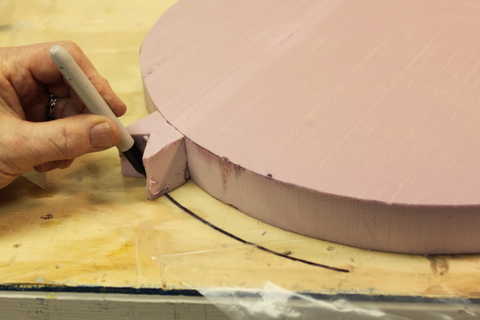
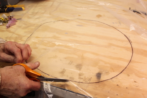 Figure 3: (left) Using a spacer to draw on the plastic. (right) Cutting the plastic.
A bag skirt is like putting an inner-tube under the hovercraft and
putting some holes in it on the bottom. Air flows out of the holes to
provide a cushion of air and the inner-tube conforms to the surface.
A wall skirt (the type we will be using, shown in
Figure 2) is basically a flexible wall going
around the hovercraft that keeps the air in and conforms to the
surface. A finger skirt consists of large number of small triangular
segments and is similar to the wall skirt except it is able to handle
a more varied terrain as each segment of the skirt is more flexible
and independent of the other segments.
To construct a wall skirt we will use 5mil plastic sheeting. Through
experimentation I found that this particular type and thickness
plastic resulted in a good skirt for this size hovercraft. Start by
laying the foam you cut on top of the plastic. Create a spacer out of
scrap foam to help you guide drawing a circle that is approximately
0.75 inches larger than foam circle as show in
Figure 3. Then cut out the plastic circle.
Figure 3: (left) Using a spacer to draw on the plastic. (right) Cutting the plastic.
A bag skirt is like putting an inner-tube under the hovercraft and
putting some holes in it on the bottom. Air flows out of the holes to
provide a cushion of air and the inner-tube conforms to the surface.
A wall skirt (the type we will be using, shown in
Figure 2) is basically a flexible wall going
around the hovercraft that keeps the air in and conforms to the
surface. A finger skirt consists of large number of small triangular
segments and is similar to the wall skirt except it is able to handle
a more varied terrain as each segment of the skirt is more flexible
and independent of the other segments.
To construct a wall skirt we will use 5mil plastic sheeting. Through
experimentation I found that this particular type and thickness
plastic resulted in a good skirt for this size hovercraft. Start by
laying the foam you cut on top of the plastic. Create a spacer out of
scrap foam to help you guide drawing a circle that is approximately
0.75 inches larger than foam circle as show in
Figure 3. Then cut out the plastic circle.
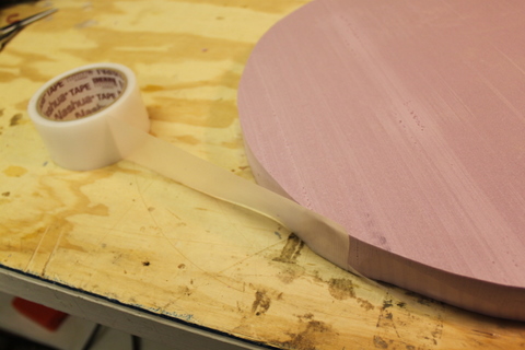 Figure 4: Taping the plastic disk to the hovercraft base.
The next step is to tape the plastic to the bottom of the hovercraft.
Place the foam over your plastic cutout and center it. Now, fold up
the plastic, it should come about half way up the edge of the foam.
As shown in Figure 4, tape the skirt all around
the hovercraft. The tape will extend slightly higher than the top of
the foam, fold this down all around. Assure that the tape is well
adhered to the foam all the way around. The plastic should now
completely cover the bottom of the hovercraft. When taping, the
plastic does not need to be completely tight to the base, but it
should have relatively even tightness all the way around.
Figure 4: Taping the plastic disk to the hovercraft base.
The next step is to tape the plastic to the bottom of the hovercraft.
Place the foam over your plastic cutout and center it. Now, fold up
the plastic, it should come about half way up the edge of the foam.
As shown in Figure 4, tape the skirt all around
the hovercraft. The tape will extend slightly higher than the top of
the foam, fold this down all around. Assure that the tape is well
adhered to the foam all the way around. The plastic should now
completely cover the bottom of the hovercraft. When taping, the
plastic does not need to be completely tight to the base, but it
should have relatively even tightness all the way around.
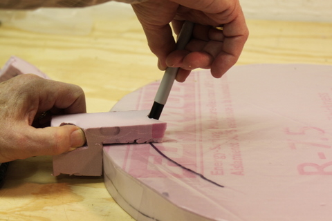
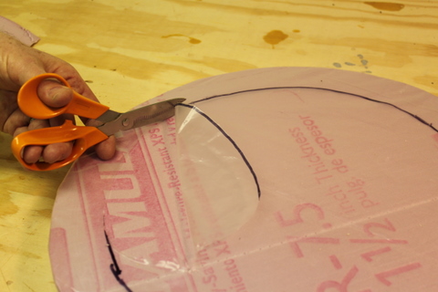 Figure 5: (left) Marking the inside of the plastic with a spacer. (right) Cutting the inside of the plastic to form the skirt.
The next step is to mark and cut a circle out of the center of the
skirt. This will leave a annulus of plastic around the edge of the
hovercraft, forming the skirt. Again, create a guide using left over
foam as shown in Figure 5. You should size it
such that there will be about 1.5 inches of plastic remaining. Then
cut out the inner circle. Try to cut smoothly, as this will be the
edge of the skirt. Figure 6 shows the resultant
skirt.
Figure 5: (left) Marking the inside of the plastic with a spacer. (right) Cutting the inside of the plastic to form the skirt.
The next step is to mark and cut a circle out of the center of the
skirt. This will leave a annulus of plastic around the edge of the
hovercraft, forming the skirt. Again, create a guide using left over
foam as shown in Figure 5. You should size it
such that there will be about 1.5 inches of plastic remaining. Then
cut out the inner circle. Try to cut smoothly, as this will be the
edge of the skirt. Figure 6 shows the resultant
skirt.
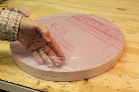 Figure 6: The resulting skirt.
Note that you may want to experiment with the efficiency of the skirt
and lift (described in Section 5) before
completing the final thruster layout in the next section. You will,
of course, have to install the lift thruster first.
Question: Describe the construction of the skirt and any problems you
encountered. Did your first skirt work as expected?
Figure 6: The resulting skirt.
Note that you may want to experiment with the efficiency of the skirt
and lift (described in Section 5) before
completing the final thruster layout in the next section. You will,
of course, have to install the lift thruster first.
Question: Describe the construction of the skirt and any problems you
encountered. Did your first skirt work as expected?
4.3 Thruster Layout
In this section we will come up with a layout for the thrusters. The
hoverboard supports a total of six thrusters. One will be used as the
lift thruster. The remaining five can be positioned in any
configuration.
4.3.1 Lift Thruster
Start by installing the lift thruster. To do so, find the center of
your hovercraft. Hold the small end of the thruster over the center
of the hovercraft. Trace this using a pen or marker and cut out the
foam. Note that the hole should be slightly small so that friction
will hold the thruster in the hole. It is best to start with a
smaller hole, as it is easier to make it larger later1. Slide the
small end of the thruster into the hole. At this point you should
probably verify that your skirt works properly by doing
Section 5.
4.3.2 Motion Thrusters
You have 5 remaining thrusters to use to control the hovercraft. The
layout of these is up to you. However, your hovercraft must be
omni-direction (must be able to translate in any direction without
needing to rotate first). In addition, you should have rotational
control. Note that the thrusters can only operate in one direction
(they can only push, not pull).
There are a couple of configurations you can use to achieve
omni-directional and rotational control. One idea is to have three
translational thrusters (120° separation) and two opposing
rotational thrusters. To move in some directions, you will have to
use multiple thrusters. You could also use four translational
thrusters (±x, ±y) and one rotational thruster. With this
configuration you may only be able to rotation in one direction
quickly, but you could potentially utilize the torque from the lift
thruster to rotate in the other direction. Finally, you could place
some of the translational thrusters at a slight angle so they would
exert a torque on the craft and produce a rotation. The choice is up
to you. It is easy to reconfigure the thrusters, so you can try a
variety of setups.
Question: What thruster configuration did you decide to use (a picture may be useful)? Why did you choose this?
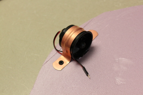 Figure 7: The mounted thruster.
To mount the thrusters we will use 1.5 inch copper pipe hangers and
screws as shown in Figure 7. These to not fit
exactly, however, you can pliers to form them to the thrusters. You
should make sure that they hold the thrusters tight against the
hovercraft, but that they do not deform the thruster housing as this
will impede the thruster. You can cut a small channel or press the
lip of the thruster into the foam to help lock it in place. Use the
1.25 inch drywall screws to secure the bracket. Do not tighten them
too much as the foam is soft and you will easily strip the hole.
Once you have soldered extension wires onto the thrusters (in the next
Section), you can bury the wires in the foam to keep them out of the
way. To do so, cut a small channel in the foam. Place the wires in
the channels and then tape over them to keep them inside.
Figure 7: The mounted thruster.
To mount the thrusters we will use 1.5 inch copper pipe hangers and
screws as shown in Figure 7. These to not fit
exactly, however, you can pliers to form them to the thrusters. You
should make sure that they hold the thrusters tight against the
hovercraft, but that they do not deform the thruster housing as this
will impede the thruster. You can cut a small channel or press the
lip of the thruster into the foam to help lock it in place. Use the
1.25 inch drywall screws to secure the bracket. Do not tighten them
too much as the foam is soft and you will easily strip the hole.
Once you have soldered extension wires onto the thrusters (in the next
Section), you can bury the wires in the foam to keep them out of the
way. To do so, cut a small channel in the foam. Place the wires in
the channels and then tape over them to keep them inside.
4.4 Soldering Thruster Wires
The wires on the thrusters are too short to reach a single location
where the hoverboard will be mounted. You will need to extend the
wires to reach a single location where the hoverboard will be mounted.
The hoverboard is 2 by 4 inches and the motor connectors are located
in one corner of the board. Pick a location for the hoverboard and
determine the rough length of the each of the wires needed to reach
this location.
Cut the existing thruster wires such that each end of the wires are at
least 1 inch long. We will use the existing connectors on the
thrusters and insert a segment of wire by soldering to make them
longer. Soldering is an important skill that always comes in useful
when working with embedded systems. In class you saw a demonstration
of how to solder wires. This is the basic technique that you will
use. All of the components on the hoverboards were soldered by hand
using similar techniques.
Now cut a segment of red and black wire from the spools that will be
long enough to enable the thrusters to reach the hoverboard location
(note that it is better to have it slightly too long versus too
short). Strip approximately a quarter inch of off of each end of all
wires. Now "tin" each of the ends of all the wires, as was
demonstrated in class. Tinning is the process of applying solder to
the wires.
Now place the tinned wire ends together, perhaps having someone else
hold them for you. Heat the wires and apply a little more solder so
that they are fully soldered together. Once you have soldered all the
joints, have someone else look at them and verify that the look well
soldered. Remember that there should be solder over all the wire,
there should be significant overlap of the wires, and the solder
should be smooth, without sharp points. Once someone else verifies
that the joints look good, use electrical tape to tape all of the
wires so that nothing is exposed.
It is said that robotics is the "science of cables and connectors."
Double check that all connections are good, otherwise you may run into
trouble later when a thruster stops working for an unknown reason. It
also may be a good idea to test each individual thruster before and
after adding the extension to verify that they function.
Everyone in your group should solder at least one thruster.
5 Hovercraft Experiments
Now that you have designed and assembled your hovercraft, it is time
to test how well it lifts. Note that you may find that you need to
redo your skirt if the performance is not very good. Typical problems
include loud vibrations, high friction, or air gushing out of one side
or another. Sometimes it is possible to fix these problems by adding
or removing weight from the hovercraft or adjusting the balance.
Question: Report on how well the skirt of your hovercraft works. Did
the first version work? If not, what were the problems and how did
you overcome them?
5.1 Powering Thrusters
Note, the thrusters are somewhat inexpensive and I have found
that they may die if run consecutively for longer than 10 minutes at
a time. Try to limit using the thrusters to times when you actually
need to use them. Do not leave them running if you are not actively
performing experiments. The symptoms you will see if you do run
them for too long are that the thrust output will decrease
significantly or it will stop completely. I suspect that this is
due to motor overheating, although it could be caused by other
problems (e.g. worn brushes). Let me know if any of your motors
fail and please try to describe the usage characteristics.
As we are not yet using the Hoverboard, we will be using a power
supply to power the thrusters. Before powering a thruster connected
to the hoverboard, we will power a thruster that is not connected to
anything. If you have already connected all of your thrusters,
temporarily remove one for these experiments.
The power supplies have a maximum current rating of 2.5A and go up to
30V. You should start by setting the voltage to 8.4V. This is near
the voltage of the batteries that we will be using later in the
course. A number of extension cables have been provided that enable
connecting the power supply to the thrusters. Without the thruster
connected to anything, locate one of the extension cables and plug the
red wire into the positive (+) terminal of the power supply and the
black wire into the negative (-) terminal. Most systems use red to
indicate positive voltage and black to indicate negative, however,
this is just a convention so do not rely on it.
Question: The thrusters have a rated power of about 41W at 8.4V. How
many Amps do they draw? The power supply cannot supply this much
power.
With the voltage set to 8.4V, set the current control nob to a middle
position. Have one person hold the casing of the thruster firmly,
keeping fingers away from the blades. Another person should then
connect the thruster to the power supply, red-to-red and
black-to-black. Note that there may be a small spark and the motor
will "jump" as it turns on.
Question: What is the voltage and current reading on the power supply?
How much power is the motor using?
Disconnect the thruster from the power supply. Repeat this experiment
with different (higher and lower) current limits.
Question: Record the voltage and current for a number of settings and
report this and the total power usage. What is the minimum current
that enables the motor to turn on?
Now, set the current limit the maximum and repeat these experiments by
varying the voltage from 0.0V to 8.4V.
Question: Report your findings for these experiments. Explain the
similarities or discrepancies from the initial experiment.
Question: Is all of the power converted into thrust? Where does the
rest go?
5.2 Lift Experiments
Now, instead of connecting the power supply to a thruster you are
holding, connect it to the main lift thruster. Start with a power
setting just slightly above the power needed to start the motor.
Slowly increase this until the hovercraft glides smoothly on your
workbench surface. Note that if you have problems (excessive
vibration, high friction, air venting, etc.), you may need to
redistribute the weight on your hovercraft, increase the weight, or
redo your skirt.
Question: How much power do you need to supply to the lift thruster to
create low friction hovering on your workbench? How about when it is
on the carpet or other surfaces?
There are pulleys, string, and weights (lots of nails that you can
measure with the scale, please put them back in their boxes when you
are done) in the lab. We will use these to characterize the forces
needed to move the hovercraft with different lift power and different
payload weights. Connect one end of the string to the hovercraft,
thread the other end through the pulley, and finally connect the other
end of the string to a weight. By holding the pulley at the edge of
the table, you can drop the weight and determine the minimum weight
needed to move the hovercraft. You can also time how long it takes to
move the hovercraft a fixed distance.
Question: Perform a number of trials to characterize the performance
of the hovercraft. Use different weights to pull the hovercraft,
different lift thrust levels, and try adding more weight to your
hovercraft (e.g. place a book on top of it without covering the lift
thruster). Which lift thrust level results in the least friction?
Does it continue to decrease when you increase the thrust, or does it
level off? Discuss the results of all of these experiments and
include any descriptive plots.
Question: (not required) Compute the friction of the hovercraft for
various thrust levels. Please show work and describe your reasoning.
Question: (not required) Repeat some of these experiments on different
surfaces.
5.3 Thrust Experiments
These experiments will require two power supplies. Use one to power
the lift thruster at a level of low friction and the other to power
one of your translational thrusters. Remember to disconnect the lift
thruster when you are not actively performing experiments. Also, do
not run it for longer than 10 minutes at a time without a few minute
break. This will help to prevent damage to the thrusters.
In these experiments we will continue to use the rope, pulley, and
weights, but now we will use them to characterize the translational
thrusters. Start with the weight near the ground and the hovercraft
near the pulley with the rope connected near the translational
thruster you will be testing. Now engage the thruster.
Question: How much weight can the thruster lift? What about at
different thruster power levels? Convert this into a thrust force,
assuming zero friction, by determining the maximum weight that the
hovercraft can move and recall F=ma and on earth a=g=9.81m/s2.
Now we will characterize the rotational speed of your hovercraft.
Time how long it takes to rotate a full rotation clockwise and
counterclockwise. For accurate results you may want to repeat this
several times and/or count how long it takes to achieve multiple
rotations.
Question: Report and analyze the results of your rotational
experiments at different thrust levels.
Question: Does the hovercraft translate when you do this? If so, do
you think it will be possible to compensate for this using the
translational thrusters?
Question: Is the rotational speed constant? Or does it increase over
time? Is there a maximum rotational speed? Does it achieve this
quickly or slowly. For example, is the rotational speed just as fast
in the first quarter turn as it is in the last quarter turn?
Question: Does the rotational speed change on different surfaces?
6 To Hand In
You should designate one person from your group as the point person
for this lab (each person needs to do this at least once over the
semester). This person is responsible for organizing and handing in
the report, but everyone must contribute to writing the text. You
should list all group members and indicate who was the point person on
this lab. Your lab should be submitted by email before the start of
class on the due date. A pdf formatted document is preferred.
Your lab report should have an introduction and conclusion and address
the various questions (highlighted as Question: ) throughout the lab in
detail. It should be well written and have a logical flow. Including
pictures, charts, and graphs may be useful in explaining the results.
There is no set page limit, but you should make sure to answer
questions in detail and explain how you arrived at your decisions.
You are also welcome to add additional insights and material to the
lab beyond answering the required questions.
N.B. This is part (a) of Lab 1. You should complete a single
lab report for all of Lab 1. However, you should start writing your
lab report now, do not wait until you have completed all of the lab.
Question: You should make sure to include a picture of your final hovercraft.
Question: Robots like to have names, what are you going to call your hovercraft?
Question: For everyone in your group how many hours did each person spend on this part and the lab in total? Did you divide the work, if so how? Work on everything together?
Question: Please discuss and highlight any areas of this lab that you
found unclear or difficult.
7 Appendix: Material Availability
Most materials (foam, brackets, screws, etc.) are available at any
hardware store. The 5mil plastic, used for the skirt, is available in
a number of places, however, I found that the 5mil plastic available
at Ace Hardware on rolls (cut to length, intended for covering
windows) is the right thickness and flexibility for the skirt. Other
plastics tended to vibrate. I am not sure the exact type of plastic
(as it was not labeled in the store), but I have found it in a number
of Ace Hardware stores in a variety of states.
The thrusters (ducted fan EDF40) were purchased online at
towerhobbies.com and are part number GWSG4000 or L5HHN906. They may
be available other places and there are certainly other ducted fans
that work well. A good alternative for a lift motor is an air
mattress pump, although most are larger than the ducted fans. The
same hovercraft design can be enlarged fairly easily to carry a person
in which case a leaf blower works well as a lift pump (and thicker
skirt plastic may be needed).
Footnotes:
1If you
do happen to make it too large, you can create another hole in a
different location as the lift thruster does not need to be exactly
in the center. Cover over your old hole with tape
File translated from
TEX
by
TTH,
version 3.89.
On 21 Jan 2011, 11:39.