*arg max *arg min
CSCE 236 Embedded Systems, Spring 2013
Lab 1


Thursday, January 24, 2012
Names of Group Members:


1  Instructions

This is a group assignment to work on during class. You only need to hand in one copy of this, but make sure that the names of all of your group members are on this sheet to receive credit. Complete all of the sections below and make sure to get the instructor or TA to sign off where required. You should keep your own notes on what you complete since parts of future homework will build on this lab.
In this lab you will learn to connect and wire basic components on a breadboard. You will interface with a button and a RGB LED and will explore how long it takes to perform various operations on different integer types.
Before starting this lab, make sure you are familiar with the layout of the breadboard and how each location is connected to each other. If you are unsure ask the instructor before you break something!

2  Resistors

In this lab you will be using 100, 180, and 47,000 (47k) ohm resistors. These are identified by different color stripes on them. You can refer to:
http://en.wikipedia.org/wiki/Electronic_color_code
to figure out the color coding scheme, but for your reference the 100 ohm resistor has the color code brown-black-brown-yellow, the 180 ohm is brown-gray(blueish)-brown-yellow, and the 47k is yellow-violet-orange-yellow. You should have three 100 ohm, three 180 ohm, and two 47k resistors in your packet.

3  LEDs

figures/ledSchematic/ledSchematic.png
Figure 1: Schematic diagram for the LED connections.
   
figures/led/led.png
Figure 2: RGB Common Cathode LED (YSL-R596CR3G4B5W-F12).

For this seciton, you will be using a tri-color RGB LED. On the breadboard, implement the circuit defined by the schematic in Figure 1, but do not connect it to the Arduino yet. You should refer to Figure 2 to determine the pin-to-color mapping of the LED.
Checkoff: Once you have completed wiring on the breadboard, have the instructor verify the connections before moving onto the next section.
Now connect the circuit on your breadboard to the proper pins on your Arduino. The pins (PD5, PD6, PD7) are given in terms of the pin names on the Atmel, you will need to determine the correct correspondence to the output pins on the Arduino itself by refering to the Arduino schematic. Write the code1 for your Arduino to turn on and off each of these LEDs2. Does the LED turn on when the output pin is high or low? For ease of use, you may want to define variable or macros that lets you turn on/off a particular color LED by name instead of pin number.
Checkoff: Write code that continually cycles through the pattern R,RG,G,GB,B,RB,ALL_OFF where RG means the red and green LED should be on at the same time. Show your completed program to an instructor for checkoff. I suggest that you put all of the code for this question in single function that you continually call from the loop function. That way you can easily comment it out when you work on the next part of this lab, without having to delete any code.

4  Button Input

figures/buttonDrawing/buttonDrawing.jpg
Figure 3: Dimensions and internal connection diagram for the button.
   
figures/buttonSchematic/buttonSchematic.png
Figure 4: Schematic diagram for the button connection.

Figure 4 shows a schematic for connecting the button to the Arduino and Figure 3 gives details on the button itself. Looking at Figure 3 you can see that when the button is pressed all of the terminals are connected together. When it is not pressed, the terminals close to each other are not connected, but those across from each other are. Following the schematic in Figure 4, connect the button to the Arduino, if you are unsure how to properly wire this connection, please ask an instructor. Note that you should connect the button to the Atmel pin PC2. This corresponds to one of the "Analog In" pins on the Arduino. Write the code to determine if the button is pressed or not. You can still use the digitalRead() function to read these pins, look at the Arduino code reference to find out how. Alternatively, you can just manually configure the Arduino registers to do this.
Checkoff: Write code that changes the color of the LED from red to green when the button is pressed and held.

5  Operation Timing

It is often useful to time how long a particular operation takes on an embedded system to ensure proper functionality. Most operations happen very quickly, but by executing the same operation many times (by putting it in a loop) you can determine how long an operation takes by simply using an LED and stopwatch. The problem is that the loop itself will incur some overhead. To further complicate this problem on an 8-bit processor, such as our Atmel, this overhead will be dependent on whether the loop counter is 8-, 16-, or 32-bits.
In this section, you should determine how long each iteration of a for loop takes when using an 8-, 16-, and 32-bit unsigned integer as the loop counter (uint8_t, uint16_t, and uint32_t, respectively). To do this, turn on an LED before entering the for loop and then turn it off once the for loop is complete. The compiler will optimize out any code that does not do anything, so we need to add an instruction that prevents this. You can do this by adding an assembly command (which the compiler will not remove) that does nothing. The easiest is to use the "nop" (no operation) command. To do this in c do (for the 8-bit version):
for(uint8_t i = 0; i < 255; i++){
  asm volatile("nop");
}

You should then experiment until you come up with values that make the LED stay on for somewhere between 5 and 15 seconds. This is sufficiently long that you can get a good estimate of how long each iteration takes by timing this overall time with a stopwatch. Note that for the 8-bit and 16-bit variables you may need to nest loops to delay for a sufficiently long period. In this case you can ignore any overhead that the nesting may cause. In addition to enabling you to time operation overhead, this will also give you an alternative, albeit less accurate, way to delay for a specific period of time as opposed to using the Arduino delay(...) function.
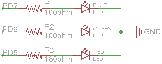
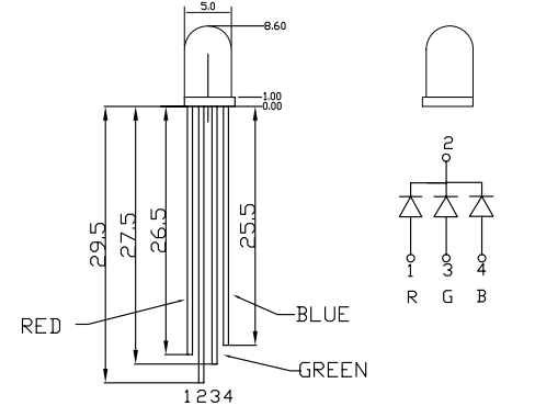
Checkoff: Write a program that uses each of the different unsigned integer types (8-, 16-, 32-bit) to turn on the red, green, and blue LEDs for 1 second each, respectively. In other words, use a uint8_t to turn on the red LED for 1 second, followed by turning on the green one for 1 second using a delay loop with the uint16_t, and finally 1 second with the blue on using a uint32_t.

Footnotes:

1You can use the Arduino pin functions or directly set registers for this lab. I suggest using the Arduino functions initially, but if you have time you should modify them to directly set the registers (for the next homework you will need to directly set registers for some questions). To set the registers directly, you should put "#include <avr/io.h>" (without quotes) at the top of your file to get all of the register definitions (DDRD, PORTD, etc).
2You should work together on this program, each group only needs one copy; however, you should make sure to share the final version of the code among the members of your group.


File translated from TEX by TTH, version 3.89.
On 21 Jan 2013, 10:55.