This is a group assignment to work on during class. You only
need to hand in one copy of this, but make sure that the names of all
of your group members are on this sheet to receive credit. Complete
all of the sections below and make sure to get the
instructor or TA to sign off where required.
You should keep your own notes on what you complete since parts of future homework
will build on this lab.
In this lab you will learn to connect and wire basic components on a
breadboard. You will interface with a button and a RGB LED and will
explore how long it takes to perform various operations on different
integer types.
Before starting this lab, make sure you are familiar with the
layout of the breadboard and how each location is connected to each
other. If you are unsure ask the instructor before you break
something!
In this lab you will be using 100, 180, and 47,000 (47k) ohm
resistors. These are identified by different color stripes on them.
You can refer to:
http://en.wikipedia.org/wiki/Electronic_color_code
to figure out the color coding scheme, but for your reference the 100
ohm resistor has the color code brown-black-brown-yellow, the 180 ohm
is brown-gray(blueish)-brown-yellow, and the 47k is
yellow-violet-orange-yellow. You should have three 100 ohm, three 180
ohm, and two 47k resistors in your packet.
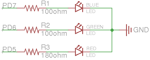
Figure 1: Schematic diagram for the LED connections.
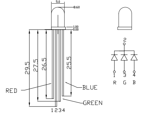
Figure 2: RGB Common Cathode LED (YSL-R596CR3G4B5W-F12).
For this seciton, you will be using a tri-color RGB LED. On the
breadboard, implement the circuit defined by the schematic in
Figure 1, but do not connect it to the Arduino yet. You
should refer to Figure 2 to determine the pin-to-color
mapping of the LED.
Checkoff:Once you have completed wiring on the breadboard, have the
instructor verify the connections before moving onto the next section.
Now connect the circuit on your breadboard to the proper pins on your
Arduino. The pins (PD5, PD6, PD7) are given in terms of the pin names
on the Atmel, you will need to determine the correct correspondence to
the output pins on the Arduino itself by refering to the Arduino
schematic. Write the code1 for your Arduino to turn on and off
each of these LEDs2. Does the LED turn on when the output pin is high or low?
For ease of use, you may want to define variable or macros that lets
you turn on/off a particular color LED by name instead of pin number.
Checkoff:Write code that continually cycles through the pattern
R,RG,G,GB,B,RB,ALL_OFF where RG means the red and green LED should
be on at the same time. Show your completed program to an
instructor for checkoff. I suggest that you put all of the code for
this question in single function that you continually call from the
loop function. That way you can easily comment it out when you work
on the next part of this lab, without having to delete any code.
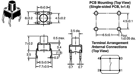
Figure 3: Dimensions and internal connection diagram for the button.
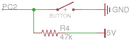
Figure 4: Schematic diagram for the button connection.
Figure 4 shows a schematic for connecting the button
to the Arduino and Figure 3 gives details on the
button itself. Looking at Figure 3 you can see
that when the button is pressed all of the terminals are connected
together. When it is not pressed, the terminals close to each other
are not connected, but those across from each other are. Following
the schematic in Figure 4, connect the button to the
Arduino, if you are unsure how to properly wire this connection,
please ask an instructor. Note that you should connect the button to
the Atmel pin PC2. This corresponds to one of the "Analog In" pins
on the Arduino. Write the code to determine if the button is pressed
or not. You can still use the digitalRead() function to read
these pins, look at the Arduino code reference to find out how.
Alternatively, you can just manually configure the Arduino registers
to do this.
Checkoff:Write code that changes the color of the LED from red to
green when the button is pressed and held.
Footnotes:
1You can use the Arduino pin
functions or directly set registers for this lab. I suggest using
the Arduino functions initially, but if you have time you should
modify them to directly set the registers (for the next homework you
will need to directly set registers for some questions). To set the
registers directly, you should put "#include <avr/io.h>" (without
quotes) at the top of your file to get all of the register
definitions (DDRD, PORTD, etc).
2You should work together on this program,
each group only needs one copy; however, you should make sure to
share the final version of the code among the members of your
group.
File translated from
TEX
by
TTH,
version 3.89. On 30 Jan 2014, 14:13.